For 1990-2009 cars only
Removal Procedure
- Remove the instrument panel (I/P) trim pad. Refer to Instrument Panel Trim Pad Replacement .
- Outboard bolster only. Reposition the I/P accessory wiring junction block. Refer to Accessory Wiring Junction Block Replacement in Wiring Systems.
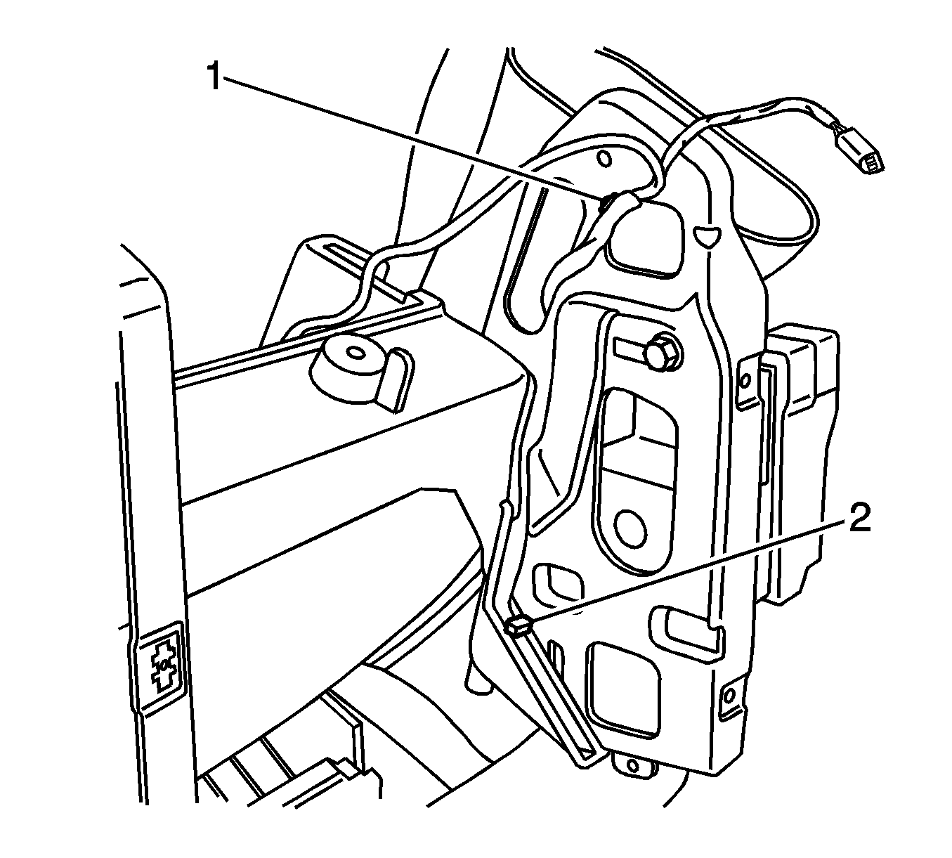
- Outboard bolster only. Disconnect the wiring harness retainers (1, 2) from the I/P passenger knee bolster.
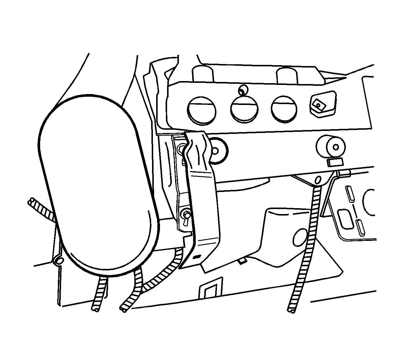
- Remove the I/P passenger knee bolster bolts. Inboard shown, outboard similar.
- Remove the I/P passenger knee bolster.


Installation Procedure
- Align the I/P passenger knee bolster the I/P carrier (cross car beam).
- Start the bolts by hand to avoid cross threading. Install the I/P passenger knee bolster bolts.
- Outboard bolster only. Connect the wiring harness retainers (1, 2) to the I/P passenger knee bolster.
- Outboard bolster only. Install the I/P accessory wiring junction block. Refer to Accessory Wiring Junction Block Replacement in Wiring Systems.
- Install the I/P trim pad. Refer to Instrument Panel Trim Pad Replacement .

Inboard bolster shown, outboard bolster similar.
Notice: Refer to Fastener Notice in the Preface section.
Tighten
Tighten the bolts to 10 N·m (89 lb in).

