Exhaust Manifold Replacement - Right Side 3.8L
Removal Procedure
- Remove the fuel injector sight shield. Refer to Fuel Injector Sight Shield Replacement .
- Remove the exhaust crossover pipe from the right exhaust manifold. Refer to Exhaust Crossover Pipe Replacement .
- Raise and support the vehicle. Refer to Lifting and Jacking the Vehicle in General Information.
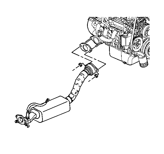
- Remove the exhaust manifold pipe stud nuts and the catalytic converter pipe from the right exhaust manifold.
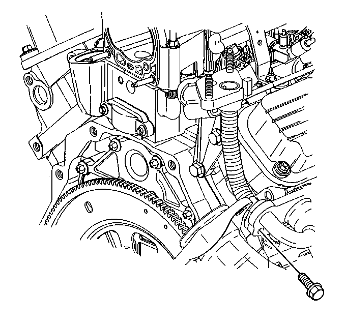
- Remove the EGR adapter pipe from the right exhaust manifold.
- Lower the vehicle.
- Rotate the engine to access the right side of the engine. Refer to Rotating the Engine for Service Access in Engine Mechanical - 3.8L.
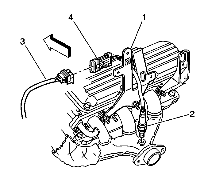
- Disconnect the heated oxygen (HO2S) sensor electrical connector (4).
- Remove the heated oxygen (HO2S) sensor electrical connector (4) from the engine sight shield bracket (1).
- Remove the right spark plug wires from the right spark plugs. Refer to Spark Plug Wire Replacement in Engine Controls - 3.8L.
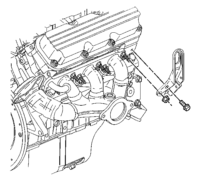
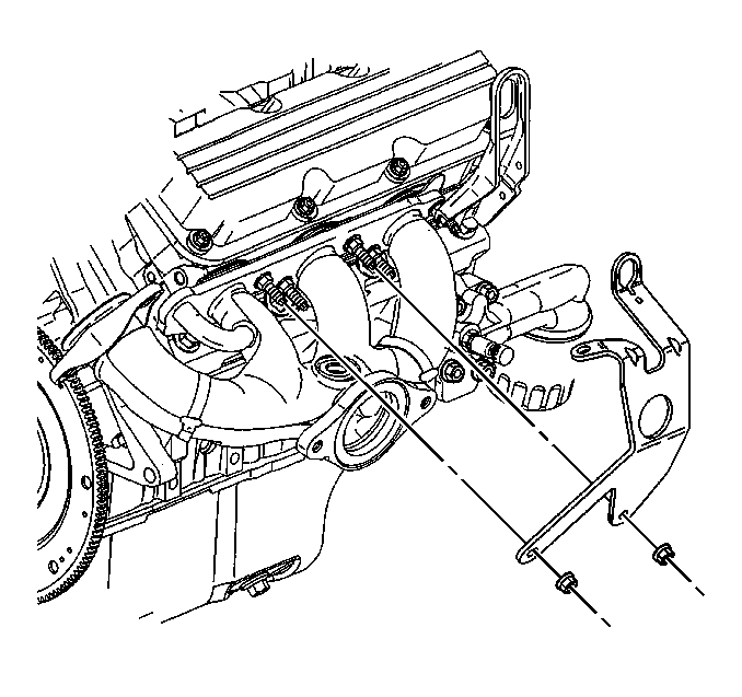
- Remove the right engine lift bracket bolt and nut.
- Remove the right engine lift bracket.
- Remove the fuel injector sight shield bracket nuts.
- Remove the fuel injector sight shield bracket.
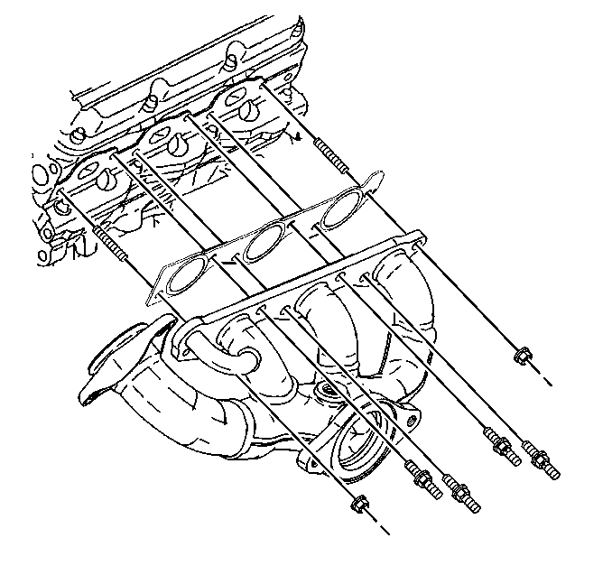
- Remove the right exhaust manifold bolts and nuts.
- Remove the right exhaust manifold.
- Remove the right exhaust manifold gasket.
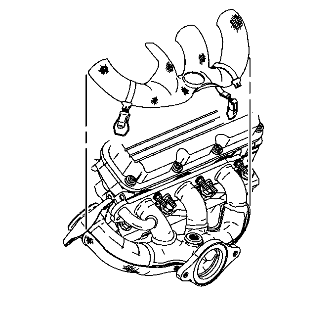
- Remove the upper right exhaust manifold heat shield.
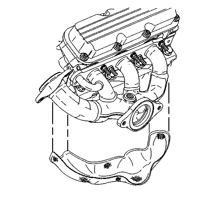
- Remove the lower right exhaust manifold heat shield.
- If replacing the right exhaust manifold remove the heated oxygen (HO2S) sensor from the right exhaust manifold. Refer to Heated Oxygen Sensor 1 Replacement in Engine Controls - 3.8L.
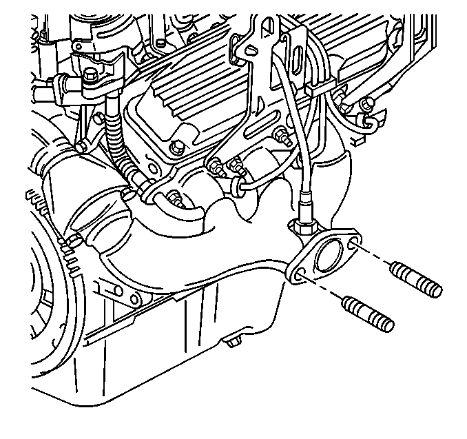
- Remove the exhaust manifold stud(s) if damaged.
- Clean and Inspect the right exhaust manifold mating surfaces
Installation Procedure
- Install the exhaust manifold stud(s) if removed.
- If replacing the right exhaust manifold Install the heated oxygen (HO2S) sensor to the right exhaust manifold. Refer to Heated Oxygen Sensor 1 Replacement in Engine Controls - 3.8L.
- Install the lower right exhaust manifold heat shield.
- Install the upper right exhaust manifold heat shield.
- Install the new right exhaust manifold gasket.
- Install the right exhaust manifold.
- Install the right exhaust manifold bolts and nuts.
- Install the fuel injector sight shield bracket.
- Install the fuel injector sight shield bracket nuts.
- Install the right engine lift bracket.
- Install the right engine lift bracket bolt and nut.
- Install the right spark plug wires. Refer to Spark Plug Wire Replacement in Engine Controls - 3.8L.
- Install the heated oxygen (HO2S) sensor electrical connector (4) to the engine sight shield bracket (1).
- Connect the heated oxygen (HO2S) sensor electrical connector (4).
- Rotate the engine to the original position.
- Raise the vehicle.
- Install the EGR adapter pipe to the right exhaust manifold.
- Install the EGR adapter pipe bolt to the right exhaust manifold.
- Install the catalytic converter pipe to the right exhaust manifold.
- Install the catalytic converter pipe stud nuts to the right exhaust manifold.
- Lower the vehicle.
- Install the exhaust crossover pipe to the right exhaust manifold. Refer to Exhaust Crossover Pipe Replacement .
- Install the fuel injector sight shield. Refer to Fuel Injector Sight Shield Replacement in Engine Mechanical - 3.8L.


Notice: Use the correct fastener in the correct location. Replacement fasteners must be the correct part number for that application. Fasteners requiring replacement or fasteners requiring the use of thread locking compound or sealant are identified in the service procedure. Do not use paints, lubricants, or corrosion inhibitors on fasteners or fastener joint surfaces unless specified. These coatings affect fastener torque and joint clamping force and may damage the fastener. Use the correct tightening sequence and specifications when installing fasteners in order to avoid damage to parts and systems.
Tighten
Tighten the right exhaust manifold bolts and nuts to 30 N·m
(22 lb ft).

Tighten
Tighten the fuel injector sight shield bracket nuts to 30 N·m
(22 lb ft).

Tighten
Tighten the right engine lift bracket bolt and nut to 30 N·m
(22 lb ft).


Tighten
Tighten the EGR adapter pipe bolt to 29 N·m (21 lb ft).

Tighten
Tighten the catalytic converter pipe stud nuts to 32 N·m
(24 lb ft).
Exhaust Manifold Replacement - Right Side 3.1L
Removal Procedure
- Disconnect the negative battery cable. Refer to Battery Negative Cable Disconnection and Connection in Engine Electrical.
- Remove the air cleaner intake duct. Refer to Air Cleaner Inlet Duct Replacement in Engine Controls - 3.1L.
- Remove the accelerator and cruise control cables with the bracket from the throttle body. Refer to Accelerator Control Cable Bracket Replacement in Engine Controls - 3.1L.
- Rotate the engine for service access. Refer to Rotating the Engine for Service Access in Engine Mechanical - 3.1L.
- Remove the manifold absolute pressure (MAP) sensor. Refer to Manifold Absolute Pressure Sensor Replacement in Engine Controls - 3.1L.
- Remove the ignition control module and the ignition control module bracket. Refer to Ignition Control Module Replacement in Engine Controls - 3.1L.
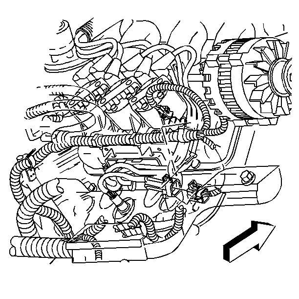
- Disconnect the heated oxygen (HO2S) sensor electrical connector.
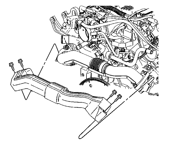
- Remove the exhaust crossover pipe heat shield bolts.
- Remove the exhaust crossover pipe heat shield.
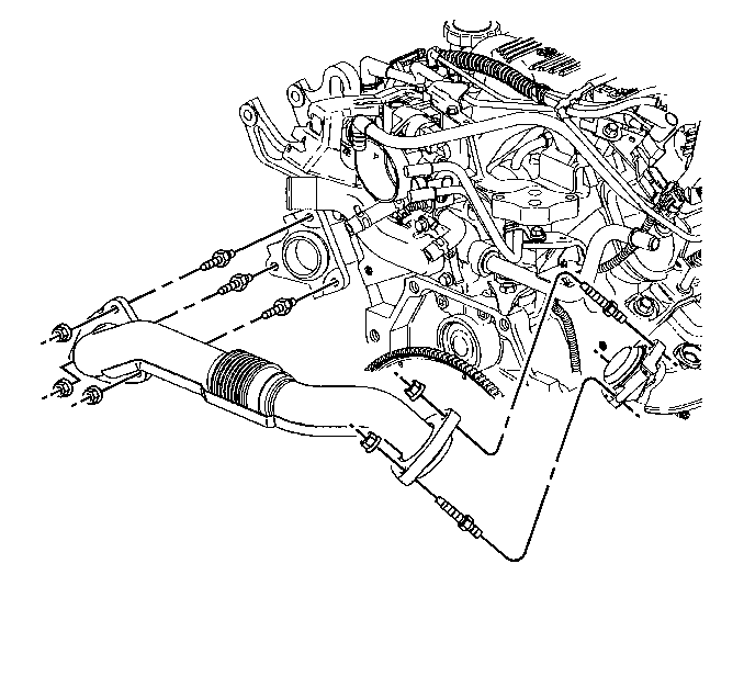
- Remove the exhaust crossover pipe nuts from the right exhaust manifold.
- Raise and support the vehicle. Refer to Lifting and Jacking the Vehicle in General Information.
- Remove the catalytic converter. Refer to Catalytic Converter Replacement .
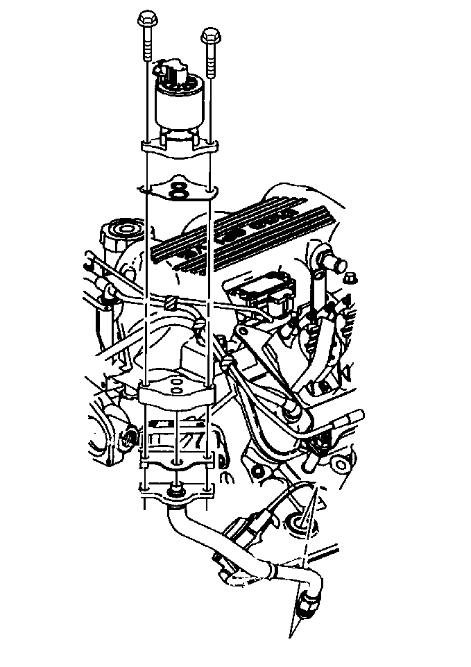
- Remove the exhaust gas recirculation (EGR) tube from the right exhaust manifold. Refer to Exhaust Gas Recirculation Pipe Replacement in Engine Controls - 3.1L.
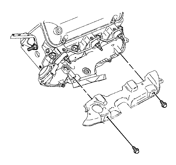
- Remove the right exhaust manifold upper heat shield bolts.
- Remove the right exhaust manifold upper heat shield.
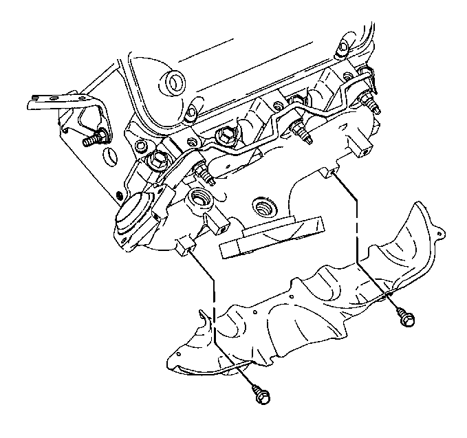
- Remove the right exhaust manifold lower heat shield bolts.
- Remove the right exhaust manifold lower heat shield.
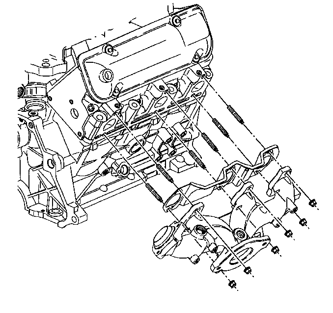
- Remove the right exhaust manifold nuts.
- Remove the right exhaust manifold.
- Remove the right exhaust manifold gasket.
- Clean and inspect the right exhaust manifold mating surfaces.
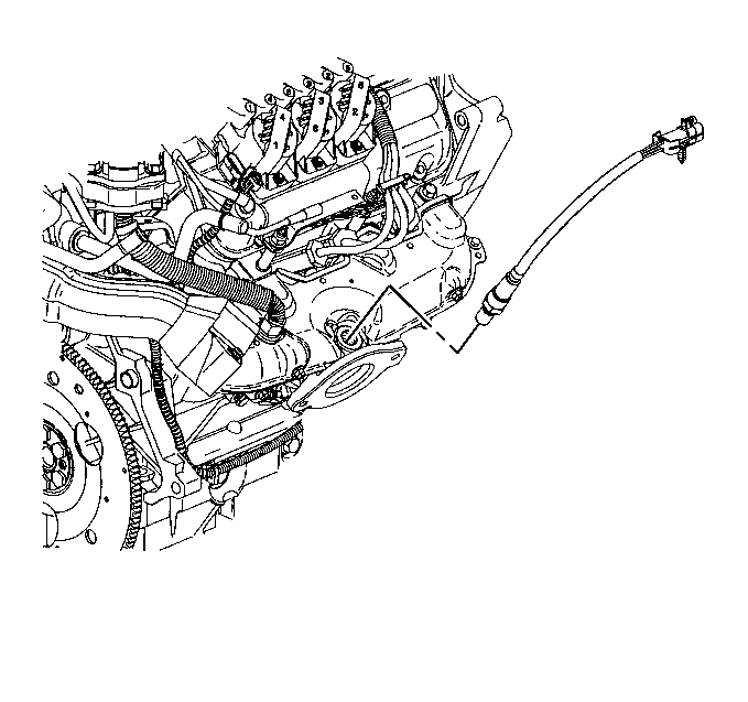
- If replacing the right exhaust manifold remove the heated oxygen (HO2S) sensor. Refer to Heated Oxygen Sensor 1 Replacement in Engine Controls - 3.1L.
Installation Procedure
- If replacing the right exhaust manifold install the heated oxygen (HO2S) sensor. Refer to Heated Oxygen Sensor 1 Replacement in Engine Controls - 3.1L.
- Install the right exhaust manifold gasket.
- Install the right exhaust manifold.
- Install the right exhaust manifold nuts.
- Install the right exhaust manifold lower heat shield.
- Install the right exhaust manifold lower heat shield bolts.
- Install the right exhaust manifold upper heat shield.
- Install the right exhaust manifold upper heat shield bolts.
- Install the exhaust gas recirculation (EGR) tube to the right exhaust manifold. Refer to Exhaust Gas Recirculation Pipe Replacement in Engine Controls - 3.1L.
- Install the catalytic converter. Refer to Catalytic Converter Replacement .
- Lower the vehicle.
- Install the exhaust crossover pipe nuts to the right exhaust manifold.
- Install the exhaust crossover pipe heat shield.
- Install the exhaust crossover pipe heat shield bolts.
- Connect the heated oxygen (HO2S) sensor electrical connector.
- Install the ignition control module and the ignition control module bracket. Refer to Ignition Control Module Replacement in Engine Controls - 3.1L.
- Install the manifold absolute pressure (MAP) sensor. Refer to Manifold Absolute Pressure Sensor Replacement in Engine Controls - 3.1L.
- Return the engine to the original position.
- Install the accelerator and cruise control cables with the bracket to the throttle body. Refer to Accelerator Control Cable Bracket Replacement in Engine Controls - 3.1L.
- Install the air cleaner intake duct. Refer to Air Cleaner Inlet Duct Replacement in Engine Controls - 3.1L.
- Connect the negative battery cable. Refer to Battery Negative Cable Disconnection and Connection in Engine Electrical.


Notice: Use the correct fastener in the correct location. Replacement fasteners must be the correct part number for that application. Fasteners requiring replacement or fasteners requiring the use of thread locking compound or sealant are identified in the service procedure. Do not use paints, lubricants, or corrosion inhibitors on fasteners or fastener joint surfaces unless specified. These coatings affect fastener torque and joint clamping force and may damage the fastener. Use the correct tightening sequence and specifications when installing fasteners in order to avoid damage to parts and systems.
Tighten
Tighten the right exhaust manifold bolts to 16 N·m (12 lb ft).

Tighten
Tighten the right exhaust manifold lower heat shield bolts to 10 N·m
(89 lb in).

Tighten
Tighten the right exhaust manifold upper heat shield bolts to 10 N·m
(89 lb in).


Tighten
Tighten the exhaust crossover pipe nuts to 25 N·m (18 lb ft).

Tighten
Tighten the exhaust crossover pipe heat shield bolts to 10 N·m
(89 lb in).

