Removal Procedure
Important: In order to minimize door realignment, do not remove both door hinges at the same time. Do each hinge separately, and replace any broken hinges first.
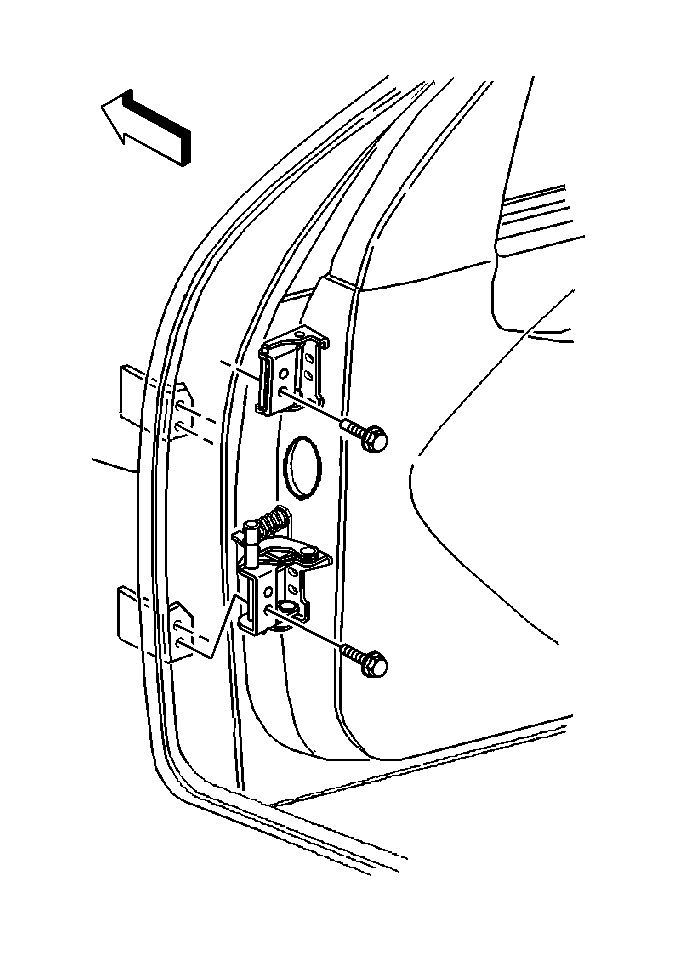
- The hinges are bolted to the door and body. The door side hinges have elongated holes which allow for some up and down, in and out adjustment. The body side hinges have elongated holes which allow for some fore and aft adjustment.
- Use a rag in order to clean the hinge mounting surfaces on the front door.
- Use a grease pencil or other suitable marker in order to mark the front door hinge location on the front door surface.
- Support the front door.
- Remove the intermediate front door hinge bolts.
- Remove the hinge spring.
- Move the door away from the front pillar as far as the conduit will allow.
- Clean the hinge mounting surfaces on the door with a rag and mark the hinge location on the door surface with a grease pencil or other suitable marker.
- Remove the bolts from the door side hinge.
- Remove the door side hinge.
- Use a rag in order to clean the hinge mounting surface on the body pillar.
- Use a grease pencil or other suitable marker in order to mark the hinge location on the body pillar.
- Remove the front fender insulator in order to gain access to the body side hinge bolts (1,2,3). Refer to Front Fender Insulator Replacement in Body Front End.
- Remove the two 13 mm body side hinge bolts (2).
- Remove the one TORX® head body side hinge bolt.
- Remove the body side hinge.
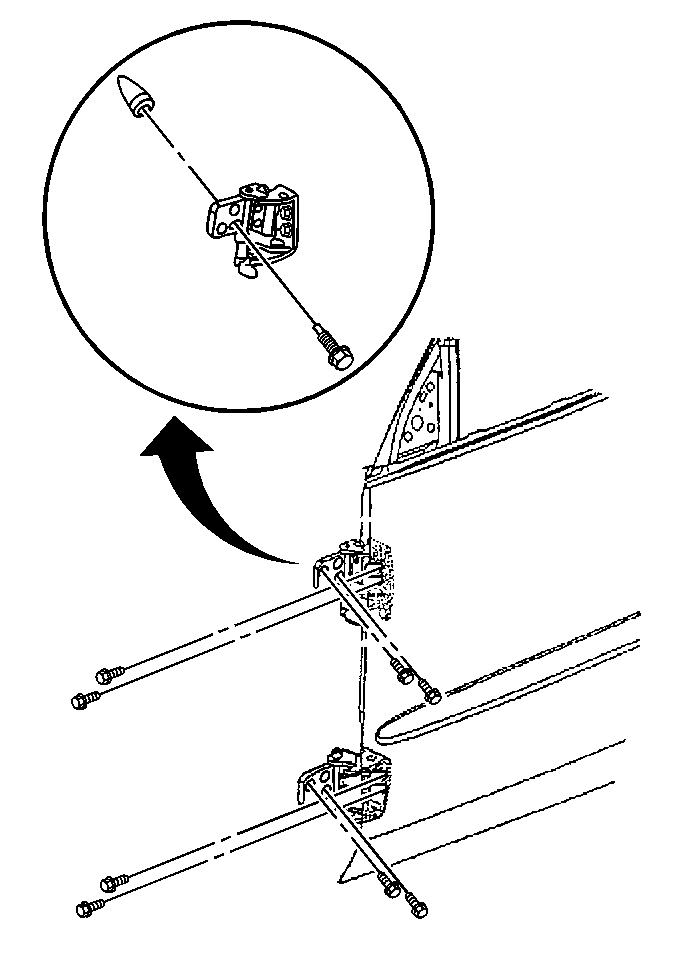
Important: The body side door hinge has the following 4 attaching bolts:
• Two 13 mm • One TORX® • One 10 mm bolt
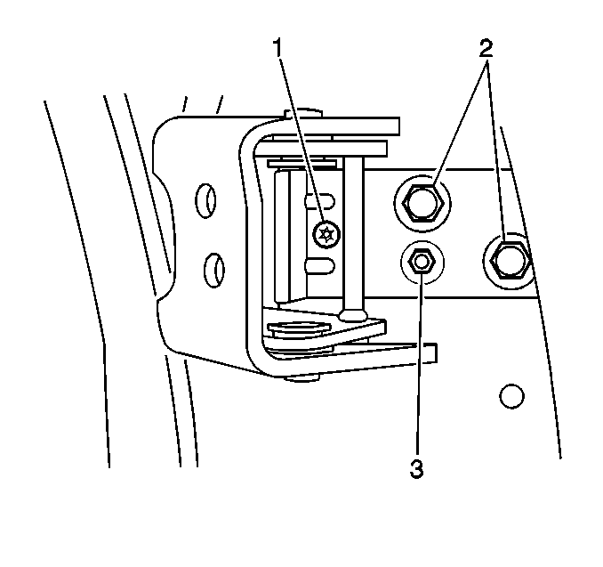
Important: Do not loosen the cone adjuster bolt (1) (10 mm hex head). The cone may fall down inside the pillar. This may create a rattle situation.
Installation Procedure
- Align the new door side hinge in position with the old alignment marks.
- Install the door side hinge bolts.
- Align the new body side hinge in position with the old alignment marks.
- Install the two 13 mm body side hinge bolts (2).
- Install the TORX® head (1) body side hinge bolt.
- Install the intermediate door hinge bolts.
- Install the front fender insulator. Refer to Front Fender Insulator Replacement in Body Front End.
- Remove the door support.
- Adjust the door. Refer to Front Side Door Adjustment .
- Close the door.
Notice: Use the correct fastener in the correct location. Replacement fasteners must be the correct part number for that application. Fasteners requiring replacement or fasteners requiring the use of thread locking compound or sealant are identified in the service procedure. Do not use paints, lubricants, or corrosion inhibitors on fasteners or fastener joint surfaces unless specified. These coatings affect fastener torque and joint clamping force and may damage the fastener. Use the correct tightening sequence and specifications when installing fasteners in order to avoid damage to parts and systems.
Tighten
Tighten the door side hinge bolts to 33 N·m (24 lb ft).
Tighten
Tighten the body side hinge bolts (2) to 33 N·m
(24 lb ft).
Tighten
Tighten the TORX® head bolt to 10 N·m (89 lb in).
Tighten
Tighten the intermediate door hinge bolts to 33 N·m (24 lb ft).
