- If removed, install the drive axle seal. Refer to
Front Wheel Drive Shaft Oil Seal Replacement
.
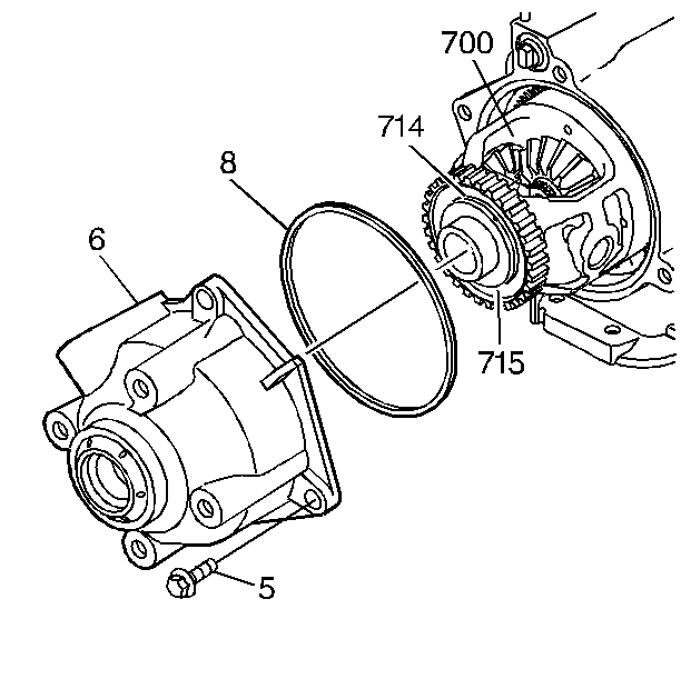
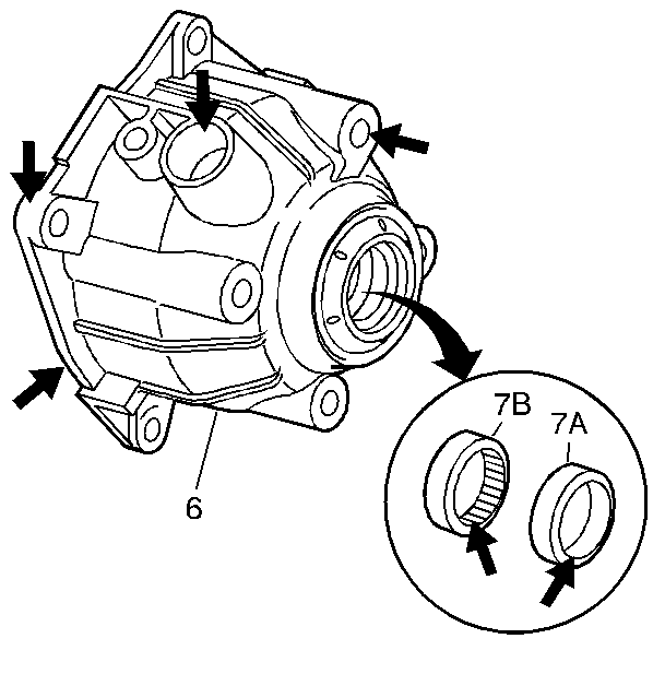
- Install the case extension housing (6) with the axle seal and the O-ring
(8).
Notice: Use the correct fastener in the correct location. Replacement fasteners
must be the correct part number for that application. Fasteners requiring
replacement or fasteners requiring the use of thread locking compound or sealant
are identified in the service procedure. Do not use paints, lubricants, or
corrosion inhibitors on fasteners or fastener joint surfaces unless specified.
These coatings affect fastener torque and joint clamping force and may damage
the fastener. Use the correct tightening sequence and specifications when
installing fasteners in order to avoid damage to parts and systems.
- Install the case
extension housing bolts (5).
Tighten
Tighten the case extension housing bolts (5) to 36 N·m
(27 lb ft).
- Install the vehicle speed sensor. Refer to
Vehicle Speed Sensor Replacement
.
- Install the transaxle brace. Refer to
Transmission Brace Replacement
.
- Connect the right drive axle to the transaxle. Refer to
Wheel Drive Shaft Replacement
in Wheel Drive Shafts.
- Lower the vehicle.
- Connect the battery ground (negative) cable. Refer to
Battery Negative Cable Disconnection and Connection
in
Engine Electrical.
Notice: Do NOT overfill the transaxle. The overfilling of the transaxle
causes foaming, loss of fluid, shift complaints, and possible damage to the
transaxle.
- Adjust the fluid level.
- Inspect for completion of the repairs.
- Inspect for fluid leaks.