Removal Procedure
Caution: When replacing the power booster brake, make sure that the cruise control cable is not routed between the booster and the cowl. If the cable is damaged or pinched, it must be replaced. Failure to do this could result in personal injury.
Notice: Inspect the locking flanges on booster and mounting plate. Replace the booster and mounting plate if the locking flanges are bent or damaged.
Tools Required
J 22805-01 Power Brake Booster Holder
- Remove the fuel injector sight shield (3800 engine only). Refer to Fuel Injector Sight Shield Replacement in Engine Mechanical.
- Remove the brake pressure modulator. Refer to Brake Pressure Modulator Valve Bracket Replacement in Antilock Brakes.
- Remove the master cylinder. Refer to Master Cylinder Replacement .
- Remove the transmission fluid filler tube.
- Refer to Transmission Fluid Filler Tube Replacement in Automatic Transaxle.
- Remove the vacuum hose from the vacuum brake booster. Refer to Vacuum Brake Booster Hose Replacement .
- Remove the vacuum brake booster pushrod from the brake pedal. Refer to Brake Pedal Replacement .
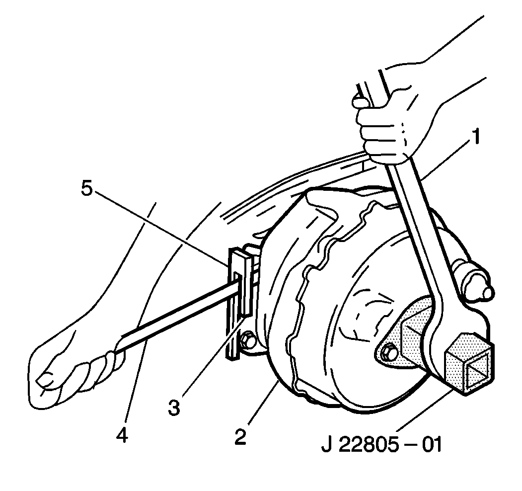
- Attach the J 22805-01 to the vacuum brake booster using the nuts.
- Unlock the vacuum brake booster (2) from the front of the dash.
- Use a screwdriver (4) in order to pry the locking tab (5) on the vacuum brake booster out of the locking notch (3) on the mounting flange. Perform the above action while turning the vacuum brake booster counterclockwise with the wrench (1) on J 22805-01 .
- Remove the vacuum brake booster (2).
Notice: When disconnecting the pushrod from the brake pedal, the brake pedal must be held stationary or damage to the brake switch may result.
Notice: Do not attempt to remove the booster until pushrod is disconnected from the brake pedal.
Notice: Use the correct fastener in the correct location. Replacement fasteners must be the correct part number for that application. Fasteners requiring replacement or fasteners requiring the use of thread locking compound or sealant are identified in the service procedure. Do not use paints, lubricants, or corrosion inhibitors on fasteners or fastener joint surfaces unless specified. These coatings affect fastener torque and joint clamping force and may damage the fastener. Use the correct tightening sequence and specifications when installing fasteners in order to avoid damage to parts and systems.
Tighten
Tighten the nuts to 27 N·m (20 lb ft).

Important: Carefully pull the pushrod through the eyehole so that you do not damage the insulator boot mounted on the front of the dash.
Installation Procedure
Notice: Internal components of this booster are not serviceable. The housing must not be unstaked and separated. Separating the housing will cause permanent deformation, preventing the booster from holding proper volume.
- Attach the J 22805-01 to the new vacuum brake booster using the nuts.
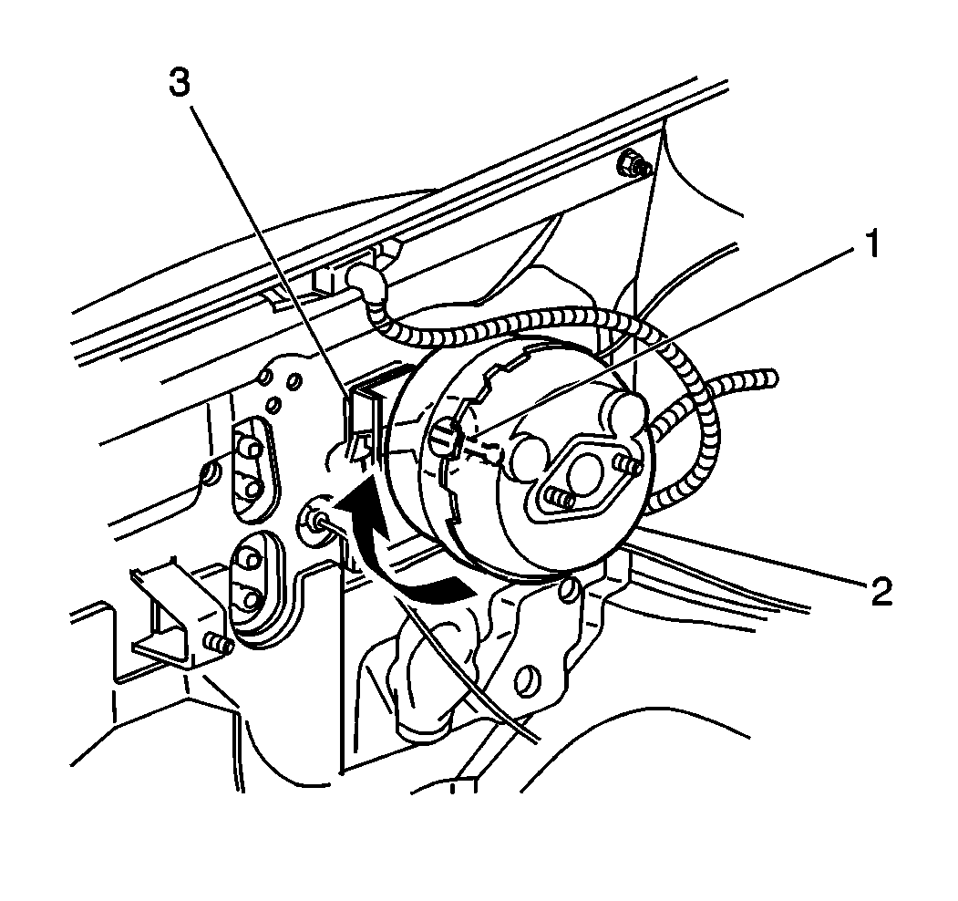
- Place the vacuum brake booster (3) on the cowl counterclockwise from the final installation position so that the locking flanges on the vacuum brake booster and on the mounting engage.
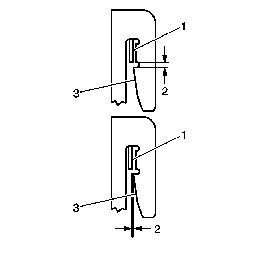
- Turn the vacuum brake booster clockwise with the wrench on the J 22805-01 . Do not use a screwdriver in the locking tab in order to install the vacuum brake booster. When the vacuum brake booster is correctly installed, the locking tab (1) slides up the flange and snaps in the locking notch (3).
- Connect the vacuum brake booster pushrod (1) to the brake pedal. Refer to. Brake Pedal Replacement .
- Install the vacuum hose to the vacuum brake booster. Refer to Vacuum Brake Booster Hose Replacement .
- Install the transmission fluid filler tube. Refer to Transmission Fluid Filler Tube Replacement in Automatic Transaxle On-Vehicle Service.
- Install the master cylinder. Refer to Master Cylinder Replacement .
- Install the fuel injector sight shield (3800 engine only). Refer to Fuel Injector Sight Shield Replacement in Engine Mechanical.
Notice: Use the correct fastener in the correct location. Replacement fasteners must be the correct part number for that application. Fasteners requiring replacement or fasteners requiring the use of thread locking compound or sealant are identified in the service procedure. Do not use paints, lubricants, or corrosion inhibitors on fasteners or fastener joint surfaces unless specified. These coatings affect fastener torque and joint clamping force and may damage the fastener. Use the correct tightening sequence and specifications when installing fasteners in order to avoid damage to parts and systems.
Tighten
Tighten the nuts to 27 N·m (20 lb ft).

Important: Carefully push the pushrod eye through the hole so that you do not damage or dislodge the insulator boot.

Important: Ensure that the locking tab (1) and the flanges are in the fully engaged position.
