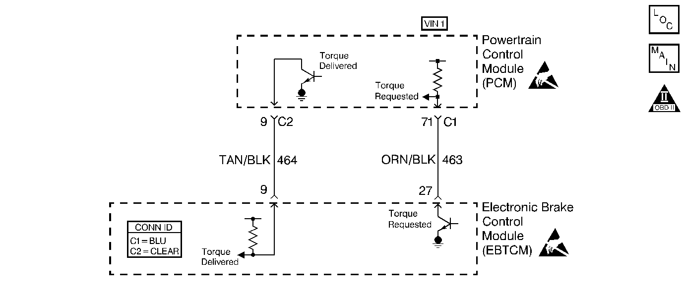
Circuit Description
The electronic brake and traction control module (EBTCM) controls the pulse width modulation (PWM) signal on the desired torque circuit while it monitors the wheel speed sensors in order to detect slippage. The PCM monitors the PWM signal, and reduces engine torque as needed by retarding the ignition timing, decreasing the boost duty cycle, increasing the air-to-fuel ratio, or, in severe cases, shutting OFF up to 3 fuel injectors. The PCM sends a PWM signal to the EBTCM on the delivered torque circuit, informing the EBTCM of the response made to the desired torque signal. A problem with the delivered torque circuit should cause DTC P1689 to set, and cause the traction control to be disabled. An ABS/TCS DTC may also be set. For further ABS/TCS DTC information, refer to ABS Description .
Conditions for Setting the DTC
| • | The ignition is ON. |
| • | An improper voltage level has been detected on output circuit for the traction control delivered torque output circuit. |
| • | The above conditions are present for at least 30 seconds. |
Action Taken When the DTC Sets
The PCM stores conditions which were present when the DTC set as Failure Records only. This information will not be stored as Freeze Frame Records.
Conditions for Clearing the MIL/DTC
| • | A history DTC will clear after 40 consecutive warm-up cycles have occurred without a malfunction. |
| • | Clear the DTC by using the scan tool Clear Info function. |
Diagnostic Aids
Inspect for the following conditions.
Many situations may lead to an intermittent condition. Perform each inspection or test as directed.
Important: : Remove any debris from the connector surfaces before servicing a component. Inspect the connector gaskets when diagnosing or replacing a component. Ensure that the gaskets are installed correctly. The gaskets prevent contaminate intrusion.
| • | Loose terminal connection |
| - | Use a corresponding mating terminal to test for proper tension. Refer to Testing for Intermittent Conditions and Poor Connections , and to Connector Repairs in Wiring Systems for diagnosis and repair. |
| - | Inspect the harness connectors for backed out terminals, improper mating, broken locks, improperly formed or damaged terminals, and faulty terminal to wire connection. Refer to Testing for Intermittent Conditions and Poor Connections , and to Connector Repairs in Wiring Systems for diagnosis and repair. |
| • | Damaged harness--Inspect the wiring harness for damage. If the harness inspection does not reveal a problem, observe the display on the scan tool while moving connectors and wiring harnesses related to the sensor. A change in the scan tool display may indicate the location of the fault. Refer to Wiring Repairs in Wiring Systems for diagnosis and repair. |
| • | Inspect the powertrain control module (PCM) and the engine grounds for clean and secure connections. Refer to Wiring Repairs in Wiring Systems for diagnosis and repair. |
If the condition is determined to be intermittent, reviewing the Snapshot or Freeze Frame/Failure Records may be useful in determining when the DTC or condition was identified.
Test Description
The numbers below refer to the step numbers on the Diagnostic Table.
-
Normally, ignition feed voltage should be present on the control circuit with the PCM disconnected and with the ignition turned ON.
-
This step tests for a shorted component, or for a short to B+ on the control circuit. Either condition will result in a measured current of more than 500 milliamps. This step also checks for a component that is opening during operations, resulting in a measured current of 0 milliamps.
-
This step tests for a short to voltage on the control circuit.
-
This vehicle is equipped with a PCM which utilizes an electrically erasable programmable read-only memory (EEPROM). When you replace the PCM, you must program the new PCM.
Step | Action | Values | Yes | No | ||||||
|---|---|---|---|---|---|---|---|---|---|---|
1 | Did you perform the Powertrain On-Board Diagnostic (OBD) System Check? | -- | ||||||||
Is the voltage near the specified value? | B+ | |||||||||
Is the current reading between the specified values? | 0.001-0.5 Amp (1-500 mA) | |||||||||
Is the voltage at the specified value? | 0 V | |||||||||
5 | Locate and repair the short to voltage in the delivered torque control circuit. Refer to Wiring Repairs in Wiring Systems. Did you complete the repair? | -- | -- | |||||||
6 |
Is the fuse open? | -- | ||||||||
7 |
Did you complete the repair? | -- | -- | |||||||
8 |
Is the voltage near the specified value? | B+ | ||||||||
9 |
Did you find and correct the condition? | -- | ||||||||
10 |
Did you find and correct the condition? | -- | ||||||||
11 |
Does the test lamp flash ON and OFF? | -- | Go to Diagnostic Aids | |||||||
12 |
Did you find and correct the condition? | -- | ||||||||
13 | Locate and repair any open in the ignition feed circuit to the EBTCM. Refer to Wiring Repairs in Wiring Systems. Did you complete the repair? | -- | -- | |||||||
14 | Replace the EBTCM. Refer to Electronic Brake and Traction Control Module Replacement in Antilock Brake System. Did you complete the replacement? | -- | -- | |||||||
|
Important:: The replacement PCM must be programmed. Refer to Powertrain Control Module Replacement/Programming . Replace the PCM. Did you complete the replacement? | -- | -- | ||||||||
16 |
Does the DTC reset? | -- | System OK |
