Basic System Operation
The fuel metering system starts with the fuel in the fuel tank. An electric fuel pump, located in the fuel tank with the gauge sending unit, pumps fuel to the fuel rail through an in-pipe fuel filter. The fuel pump is designed to provide fuel at a pressure above the pressure needed by the fuel injectors. A fuel pressure regulator in the fuel rail keeps fuel available to the fuel injectors at a constant pressure. Unused fuel is returned to the fuel tank by a separate pipe. For further information on the fuel tank, the in-pipe filter, and the fuel pipes, refer to Fuel Supply Component Description .
Accelerator Controls
The accelerator control system is a cable-type. There are no linkage adjustments. You must use the specific accelerator control cable.
Throttle Body Unit
The throttle body has a throttle plate to control the amount of air delivered to the engine. The TP sensor, MAF sensor, and IAC valve are also mounted on the throttle body.
Vacuum ports located behind the throttle plate provide the vacuum signals needed by various components. The engine coolant is directed through a coolant cavity in the throttle body in order to warm the throttle valve and in order to prevent icing.
Fuel Rail
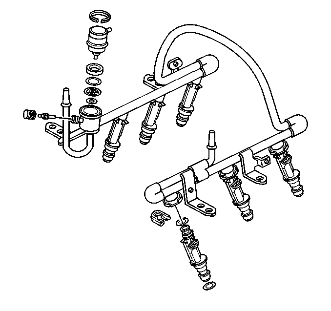
The fuel rail is mounted to the top of the engine and distributes fuel to the individual fuel injectors. The fuel is delivered to the fuel inlet tube of the fuel rail by the fuel pipes. The fuel then goes through the fuel rail to the fuel pressure regulator. The fuel pressure regulator maintains a constant fuel pressure at the fuel injectors. The remaining fuel is then returned to the fuel tank. You can observe the fuel pressure with a fuel pressure gauge at the fuel pressure gauge connection.
Fuel Injector
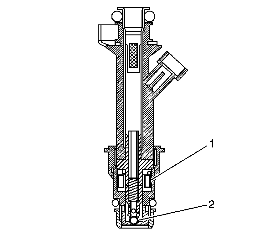
The MULTEC 2 MPFI Assembly is a solenoid operated device. It is controlled by the Powertrain Control Module (PCM), which meters the fuel to a single engine cylinder. The PCM energizes the solenoid (2) to open a normally-closed ball valve (3). This allows fuel to flow into the top of the injector (1), past the ball valve, and through a director plate at the injector outlet. The director plate has precision holes that control fuel flow, generating a spray of finely atomized fuel at the injector tip. The fuel from the injector tip is directed at the intake valve, which causes the fuel to become further atomized and vaporized before entering the combustion chamber.
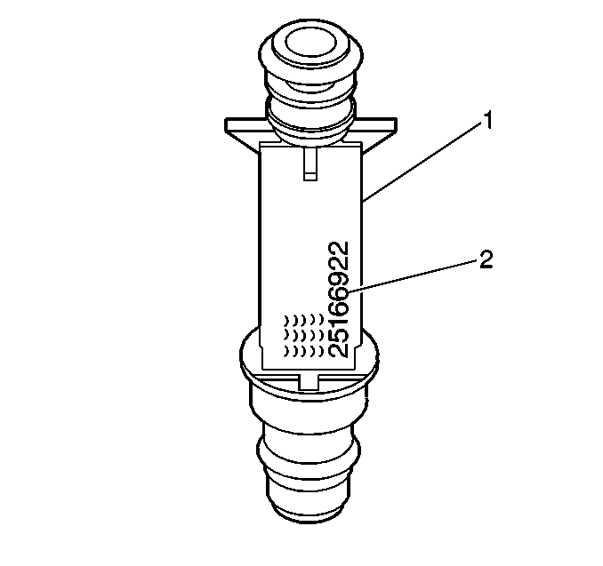
The 8-digit part number (2) is shown on the fuel injector body (1). A 4-digit number build date code is located to the far left of the part number.
Fuel Pressure Regulator
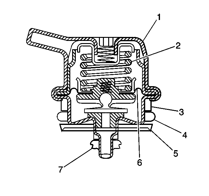
The cartridge type fuel pressure regulator (1) is a diaphragm-operated relief valve (6) with fuel pump pressure on one side, and with the regulator spring (2) pressure and the intake manifold vacuum on the other side. The regulator's function is to maintain a constant fuel pressure across the injectors at all times. The pressure regulator compensates for the engine load by increasing the fuel pressure when the engine vacuum drops.
The cartridge regulator is serviced as a separate component. When servicing the fuel pressure regulator, insure that the O-ring backup (3), the large O-ring (4), the filter screen (5), and the small O-ring (7) are properly placed on the pressure regulator.
If the fuel pressure is too low, poor performance and a DTC P0171 could result. If the pressure is too high, excessive odor and a DTC P0172 may result. Refer to Fuel System Pressure Test (VIN K) or Fuel System Pressure Test (VIN 1) for information on diagnosing fuel pressure conditions.
(3X) Reference PCM Input (CKT 430)
From the electronic ignition module, the PCM uses this signal to calculate engine speed and crankshaft position. The PCM compares the pulses on this circuit to the reference low CKT 453. The PCM also uses the pulses on this circuit in order to initiate the fuel injector pulses. If the PCM receives no pulses on this circuit, no fuel injection pulses will occur, and the engine will not run.
CAM Signal (CKT 630)
The PCM uses this signal in order to determine the position of the #1 piston during its power stroke, allowing the PCM to calculate the true Sequential Multiport Fuel Injection (SFI). A loss of this signal will set a DTC P0341. If the CAM signal is lost while the engine is running, the fuel injection system will shift to a calculated sequential fuel injection based on the last fuel injection pulse. The engine will continue to run. The engine can be restarted and will run in the calculated sequential mode as long as the fault is present, with a 1-in-6 chance of being correct. Refer to DTC P0341 Camshaft Position (CMP) Sensor Performance .
Idle Air Control (IAC) Valve
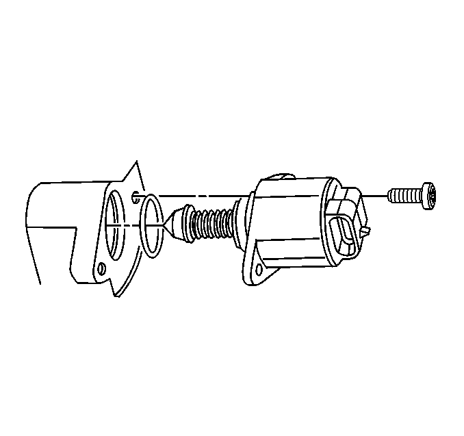
The Idle Air Control (IAC) valve controls the engine idle speed, while preventing stalls due to changes in the engine load. The IAC valve, mounted in the throttle body, controls the bypass air around the throttle plate. By moving the pintle in, in order to decrease the air flow, or out, in order to increase the air flow, a controlled amount of air can move around the throttle plate. If the RPM is too low, the PCM will retract the IAC pintle, resulting in more air being bypassed around the throttle plate in order to increase the RPM. If the RPM is too high, the PCM will extend the IAC pintle, allowing less air to be bypassed around the throttle plate, decreasing the RPM.
The IAC pintle moves in small steps called counts.
During idle, the proper position of the IAC pintle is calculated by the PCM based on the battery voltage, the coolant temperature, the engine load, and the engine RPM. If the RPM drops below a specified value, and the throttle plate is closed. If the TP sensor voltage is between 0.20-0.74, the PCM senses a near stall condition. The PCM will then calculate a new IAC pintle position in order to prevent stalls.
If the IAC valve is disconnected and reconnected with the engine running, the idle RPM will be wrong. In this condition , the IAC must be reset.
The IAC resets when the key is cycled ON, then OFF.
When you service the IAC, disconnect or connect the IAC only with the ignition OFF in order to keep from having to reset the IAC.
The position of the IAC pintle affects the engine startup and the idle characteristics of the vehicle. If the IAC pintle is open fully, too much air will be allowed into the manifold. This results in high idle speed, along with possible hard starting and a lean air/fuel ratio. DTC P0507 may set. If the IAC pintle is stuck closed, too little air will be allowed in the manifold. This results in a low idle speed, along with possible hard starting and a rich air/fuel ratio. DTC P0506 may set. If the IAC pintle is stuck part way open, the idle may be high or low, and will not respond to changes in the engine load.
Fuel Pump Electrical Circuit
When the key is first turned ON, the PCM energizes the fuel pump relay for 2 seconds in order to build up the fuel pressure quickly. If the engine is not started within 2 seconds, the PCM shuts the fuel pump OFF, and waits until the engine is cranked. When the engine is cranked and the RPM signal has been detected by the PCM, the PCM supplies 12 volts to the fuel pump relay in order to energize the electric in-tank fuel pump.
An inoperative fuel pump relay can result in a no start condition.
An inoperative fuel pump can cause a no start condition. A fuel pump which does not provide enough pressure can result in poor performance.
