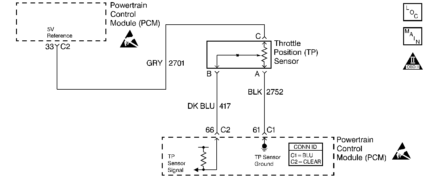
Circuit Description
The throttle position (TP) sensor circuit provides a voltage signal that changes relative to the throttle blade angle. The signal voltage will vary from less than 1 volt at closed throttle, to approximately 4 volts at wide-open throttle (WOT). The TP signal is one of the most important inputs used by the PCM for fuel control and for most of the PCM-controlled outputs. The PCM monitors the throttle position, and compares actual throttle position from the TP sensor to a predicted TP value that is calculated from the engine speed and the manifold absolute pressure (MAP). If the PCM detects an out-of-range condition, DTC P0121 will set.
Conditions for Running the DTC
| • | No TP or MAP sensor DTCs are set. |
| • | The engine is running. |
| • | The MAP is below 50 kPa in order to check for a fixed high TP sensor input. |
| • | The MAP is above 7 kPa in order to check for a fixed low TP sensor input. |
| • | The IAC Position is between 0 counts and 130 counts. |
| • | The throttle angle is steady. |
Conditions for Setting the DTC
| • | The predicted throttle angle is not close to actual throttle angle. |
| • | The above conditions are present for more than 10 seconds. |
Action Taken When the DTC Sets
| • | The PCM will illuminate the malfunction indicator lamp (MIL) during the second consecutive trip in which the diagnostic test has been run and failed. |
| • | The PCM will store conditions which were present when the DTC set as Freeze Frame/Failure Records data. |
Conditions for Clearing the MIL/DTC
| • | The PCM will turn OFF the malfunction indicator lamp (MIL) during the third consecutive trip in which the diagnostic has run and passed. |
| • | The history DTC will clear after 40 consecutive warm-up cycles have occurred without a malfunction. |
| • | The DTC can be cleared by using a scan tool. |
Diagnostic Aids
Inspect for the following conditions:
| • | A damaged or sticking throttle plate or IAC valve -- A throttle plate or an IAC valve that allows too much airflow while the throttle should be closed may cause a high idle and may cause DTC P0121 to set. Refer to Idle Air Control (IAC) System Diagnosis for diagnosis. |
| • | A skewed MAP signal or a malfunctioning MAP sensor -- An incorrect MAP signal may cause the PCM to incorrectly calculate the predicted TP sensor value during high engine load situations. Test for an unusually low MAP reading. This condition can cause DTC P0121 to set. |
Many situations may lead to an intermittent condition. Perform each inspection or test as directed.
Important: : Remove any debris from the connector surfaces before servicing a component. Inspect the connector gaskets when diagnosing or replacing a component. Ensure that the gaskets are installed correctly. The gaskets prevent contaminate intrusion.
| • | Loose terminal connection |
| - | Use a corresponding mating terminal to test for proper tension. Refer to Testing for Intermittent Conditions and Poor Connections , and to Connector Repairs in Wiring Systems for diagnosis and repair. |
| - | Inspect the harness connectors for backed out terminals, improper mating, broken locks, improperly formed or damaged terminals, and faulty terminal to wire connection. Refer to Testing for Intermittent Conditions and Poor Connections , and to Connector Repairs in Wiring Systems for diagnosis and repair. |
| • | Damaged harness--Inspect the wiring harness for damage. If the harness inspection does not reveal a problem, observe the display on the scan tool while moving connectors and wiring harnesses related to the sensor. A change in the scan tool display may indicate the location of the fault. Refer to Wiring Repairs in Wiring Systems for diagnosis and repair. |
| • | Inspect the powertrain control module (PCM) and the engine grounds for clean and secure connections. Refer to Wiring Repairs in Wiring Systems for diagnosis and repair. |
If the condition is determined to be intermittent, reviewing the Snapshot or Freeze Frame/Failure Records may be useful in determining when the DTC or condition was identified.
Test Description
The number below refers to the step number on the diagnostic table:
Step | Action | Values | Yes | No | ||||
|---|---|---|---|---|---|---|---|---|
1 | Did you perform the Powertrain On Board Diagnostic (OBD) System Check? | -- | ||||||
2 |
Important: If DTC P1635 5 Volt Reference Circuit is also set, perform that diagnostic first.
Does the TP Angle increase steadily and evenly from the closed throttle value to the wide-open throttle value?
| 0% 100% | Go to Diagnostic Aids | |||||
3 |
Is the voltage near the specified value? | 0V | ||||||
4 |
Is the voltage near the specified value? | 5V | ||||||
5 | Test the signal circuit of the TP sensor for a short to voltage. Repair the condition as necessary. Refer to Wiring Repairs in Wiring Systems. Did you find and correct the condition? | -- | ||||||
6 | Test the 5-volt reference circuit of the TP sensor for high resistance, or for a faulty connection at the PCM. Refer to Testing for Intermittent Conditions and Poor Connections and Wiring Repairs in Wiring Systems. Did you find and correct the condition? | -- | ||||||
7 | Test the signal circuit of the TP sensor for a high resistance, or for a faulty connection at the PCM. Repair the condition as necessary. Refer to Testing for Intermittent Conditions and Poor Connections and Wiring Repairs in Wiring Systems. Did you find and correct the condition? | -- | ||||||
8 | Test the ground circuit of the TP sensor for a high resistance, or for a faulty connection at the PCM. Repair the condition as necessary. Refer to Testing for Intermittent Conditions and Poor Connections and Wiring Repairs in Wiring Systems. Did you find and correct the condition? | -- | ||||||
9 | Inspect for faulty connections at the harness connector of the TP sensor. Refer to Testing for Intermittent Conditions and Poor Connections and Connector Repairs in Wiring Systems. Did you find and correct the condition? | -- | ||||||
10 | Replace the TP sensor. Refer to Throttle Position Sensor Replacement . Did you complete the replacement? | -- | -- | |||||
11 |
Important: You must program the replacement PCM. Replace the PCM. Refer to Powertrain Control Module Replacement/Programming . Did you complete the replacement? | -- | -- | |||||
Does the DTC reset? | -- | System OK |
