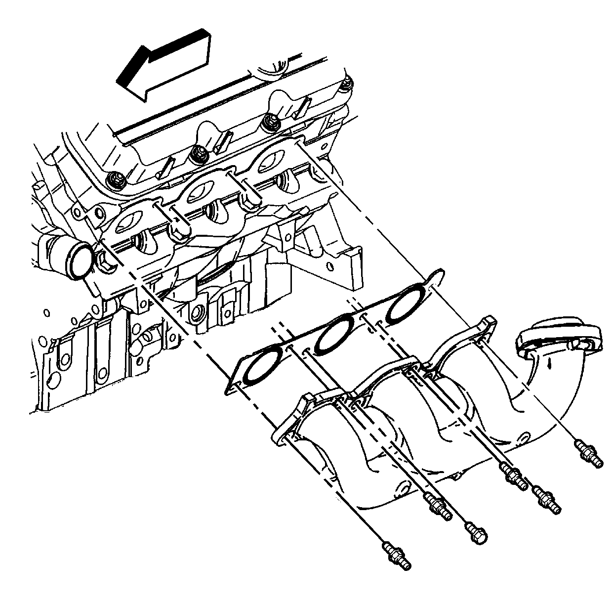
Exhaust Manifold Installation Left Side
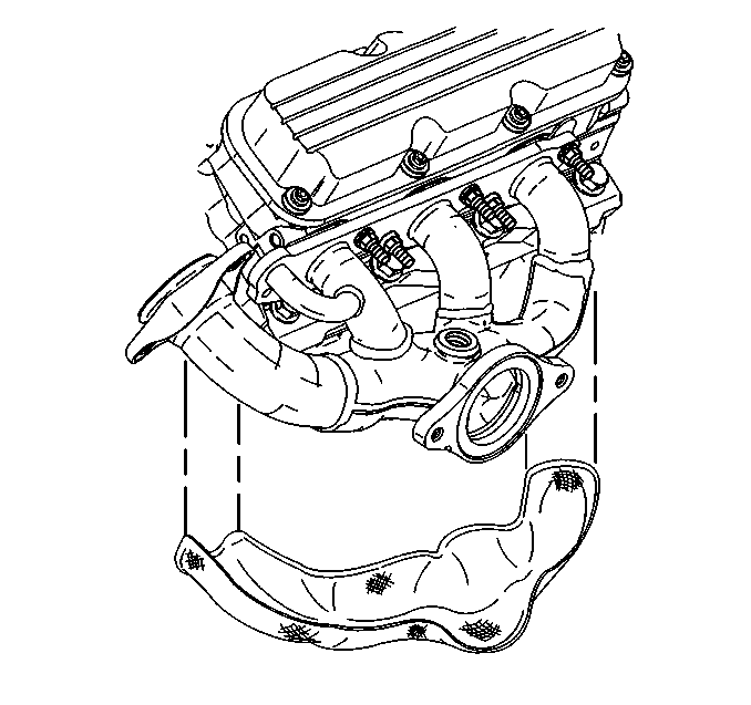
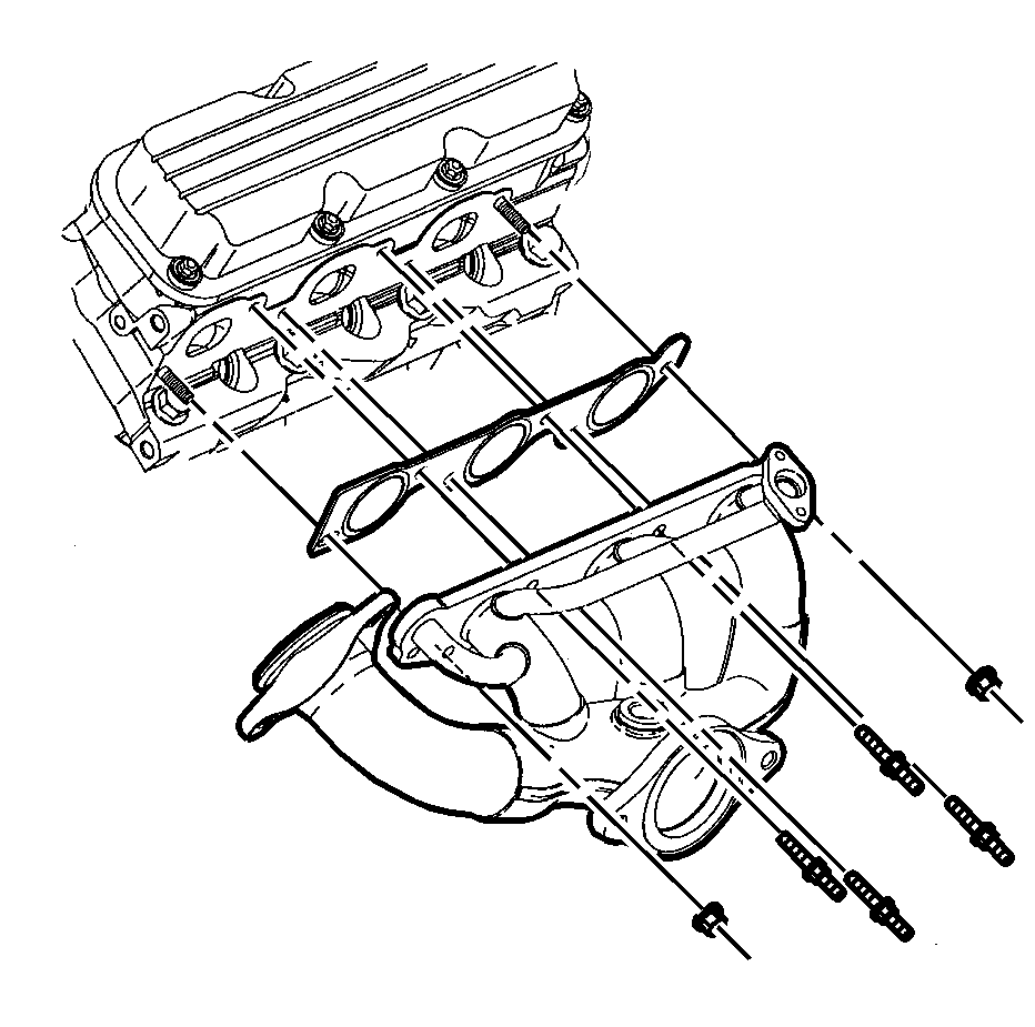
- Install the exhaust manifold gasket.
- Install the exhaust manifold.
- Install the exhaust manifold studs and bolt.
- Install the left side spark plugs.
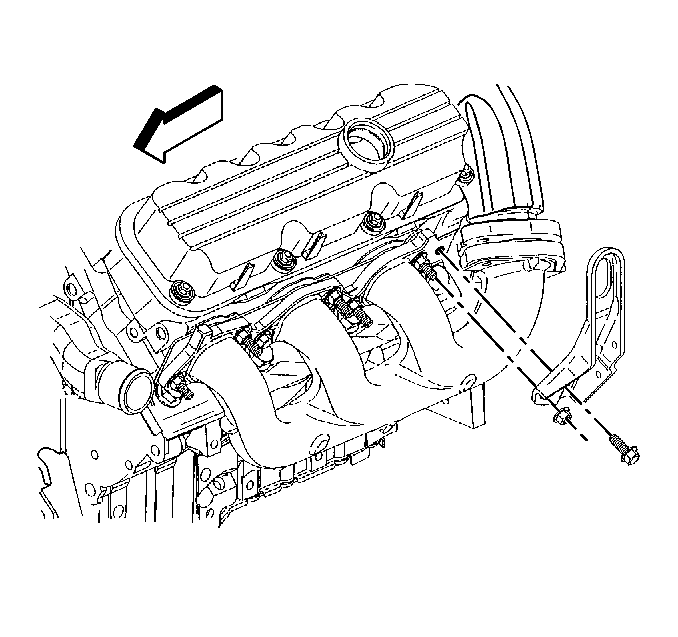
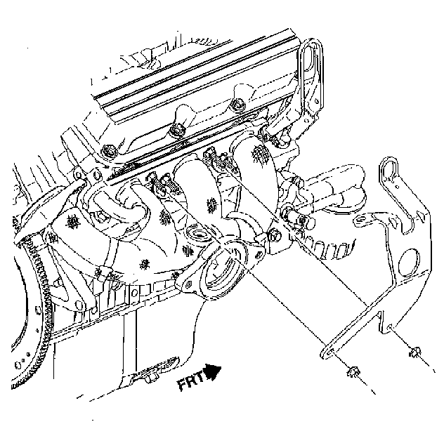
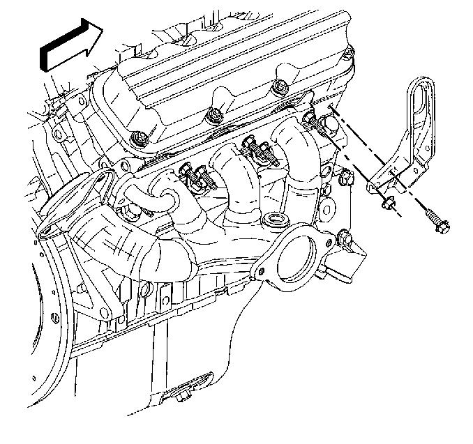
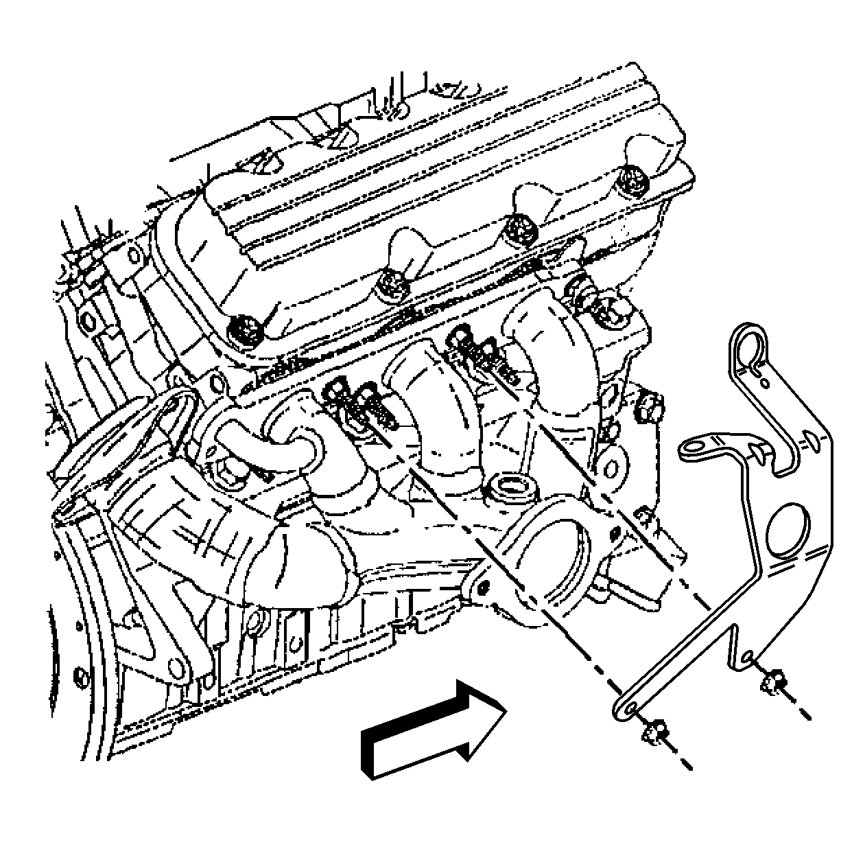
- Install the left engine lift hook.
- Install the left engine lift hook nut and bolt.
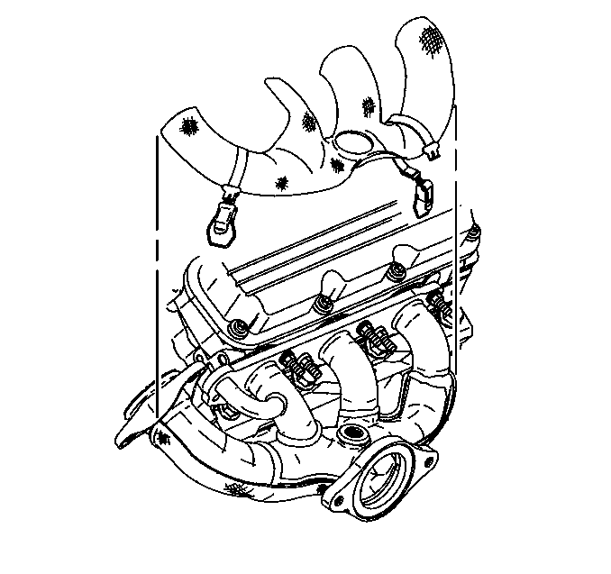
- Install the left exhaust manifold heat shield.
- Install the left exhaust manifold heat shield nuts.
Notice: Use the correct fastener in the correct location. Replacement fasteners must be the correct part number for that application. Fasteners requiring replacement or fasteners requiring the use of thread locking compound or sealant are identified in the service procedure. Do not use paints, lubricants, or corrosion inhibitors on fasteners or fastener joint surfaces unless specified. These coatings affect fastener torque and joint clamping force and may damage the fastener. Use the correct tightening sequence and specifications when installing fasteners in order to avoid damage to parts and systems.
Tighten
Tighten the exhaust manifold studs and the exhaust manifold bolt to
30 N·m (22 lb ft).
Tighten
Tighten the left side spark plugs to 27 N·m (20 lb ft).
Tighten
Tighten the left engine lift hook nut and bolt to 30 N·m
(22 lb ft).
Tighten
Tighten the left exhaust manifold heat shield nuts to 20 N·m
(15 lb ft).
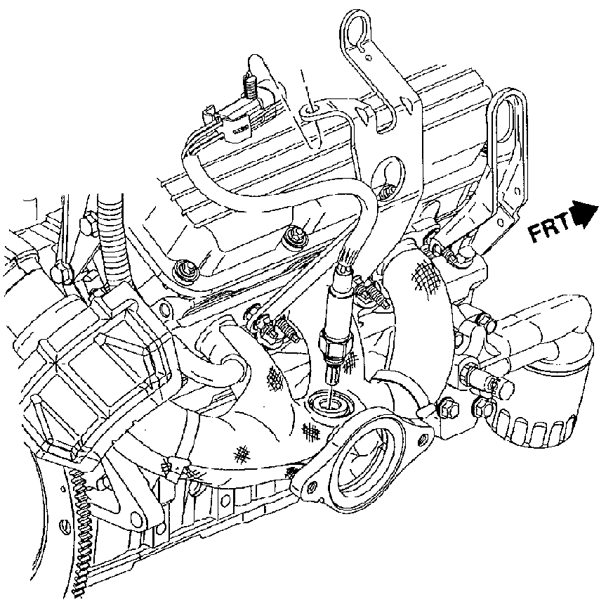
Exhaust Manifold Installation Right Side
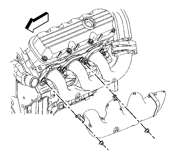
- Install the right exhaust manifold gasket.
- Install the right exhaust manifold.
- Install the right exhaust manifold studs.
- Install the fuel injector sight shield cover bracket.
- Install the fuel injector sight shield cover bracket nuts.
- Install the right engine lift hook.
- Install the right engine lift hook nut and bolt.
- Install the lower right exhaust manifold heat shield.
- Install the upper right exhaust manifold heat shield.
- Install the heated oxygen sensor lead.
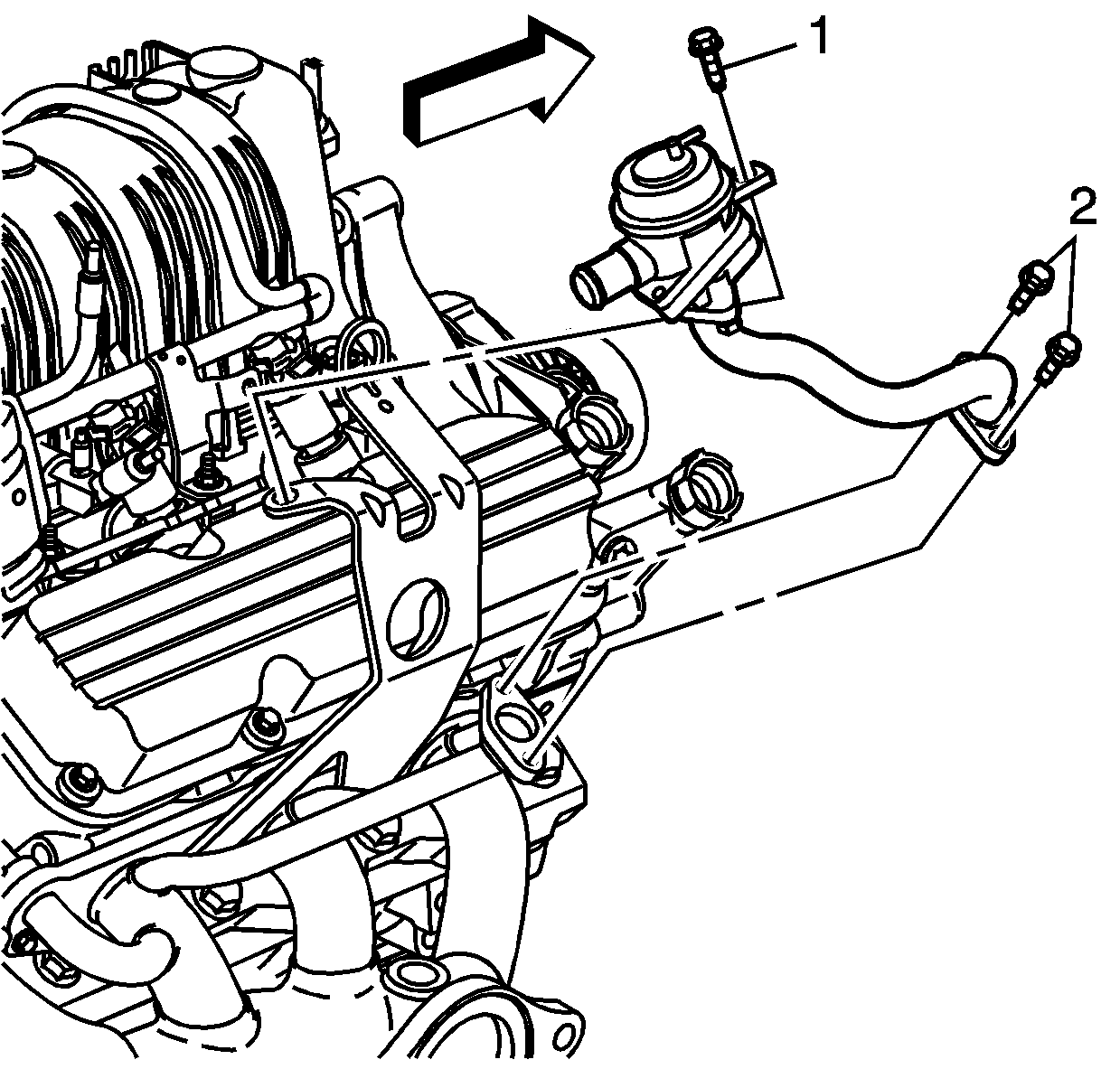
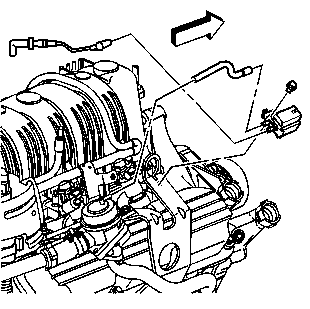
- Install the EGR mounting bracket.
- Install the EGR mounting bracket bolts.
- Install the EGR inlet pipe to the exhaust manifold.
- Install the EGR inlet pipe bolt.
Notice: Use the correct fastener in the correct location. Replacement fasteners must be the correct part number for that application. Fasteners requiring replacement or fasteners requiring the use of thread locking compound or sealant are identified in the service procedure. Do not use paints, lubricants, or corrosion inhibitors on fasteners or fastener joint surfaces unless specified. These coatings affect fastener torque and joint clamping force and may damage the fastener. Use the correct tightening sequence and specifications when installing fasteners in order to avoid damage to parts and systems.
Tighten
Tighten the right exhaust manifold studs to 30 N·m (22 lb ft).
Tighten
Tighten the fuel injector sight shield bracket nuts to 30 N·m
(22 lb ft).
Tighten
Tighten the right engine lift hook nut and bolt to 30 N·m
(22 lb ft).
Important: Inspect the EGR outlet pipe for leaks during installation. If leaks are present, replace the EGR adapter assembly.
Tighten
Tighten the EGR mounting bracket bolts to 50 N·m (37 lb ft).
Tighten
Tighten the EGR inlet pipe bolt to 29 N·m (21 lb ft).
Exhaust Manifold Installation Right Side (NC8 California Emissions)
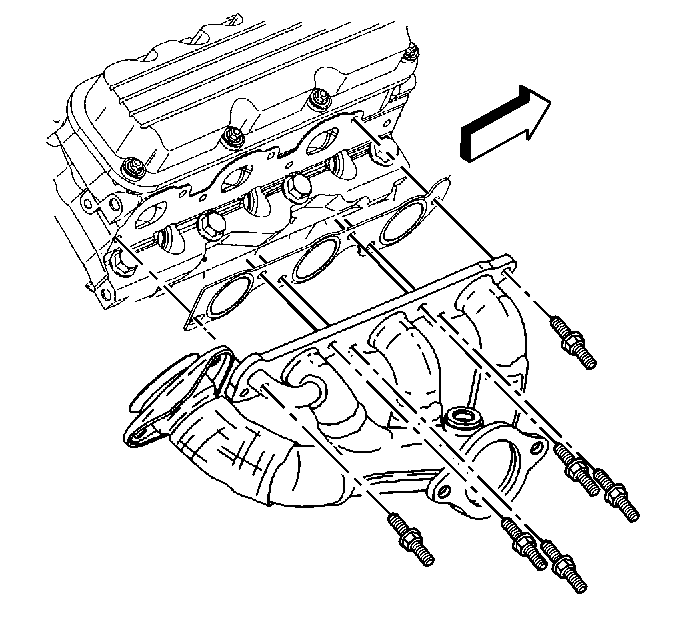
- Install the right exhaust manifold gasket.
- Install the right exhaust manifold.
- Install the right exhaust manifold studs and nuts.
- Install the right side spark plugs.
- Install the fuel injector sight shield cover bracket.
- Install the fuel injector sight shield cover bracket nuts.
- Install the right engine lift hook.
- Install the right engine lift hook nut and bolt.
- Install the lower right exhaust manifold heat shield.
- Install the upper right exhaust manifold heat shield.
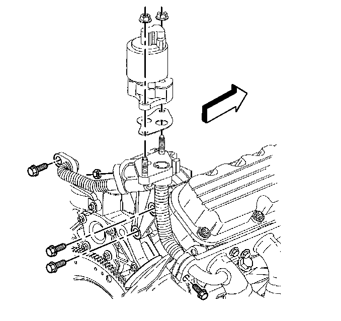
- Intall air injection check valve.
- Install air injection check valve bolts.
- Install vacuum solenoid and lines.
- Install the vacuum solenoid bolt.
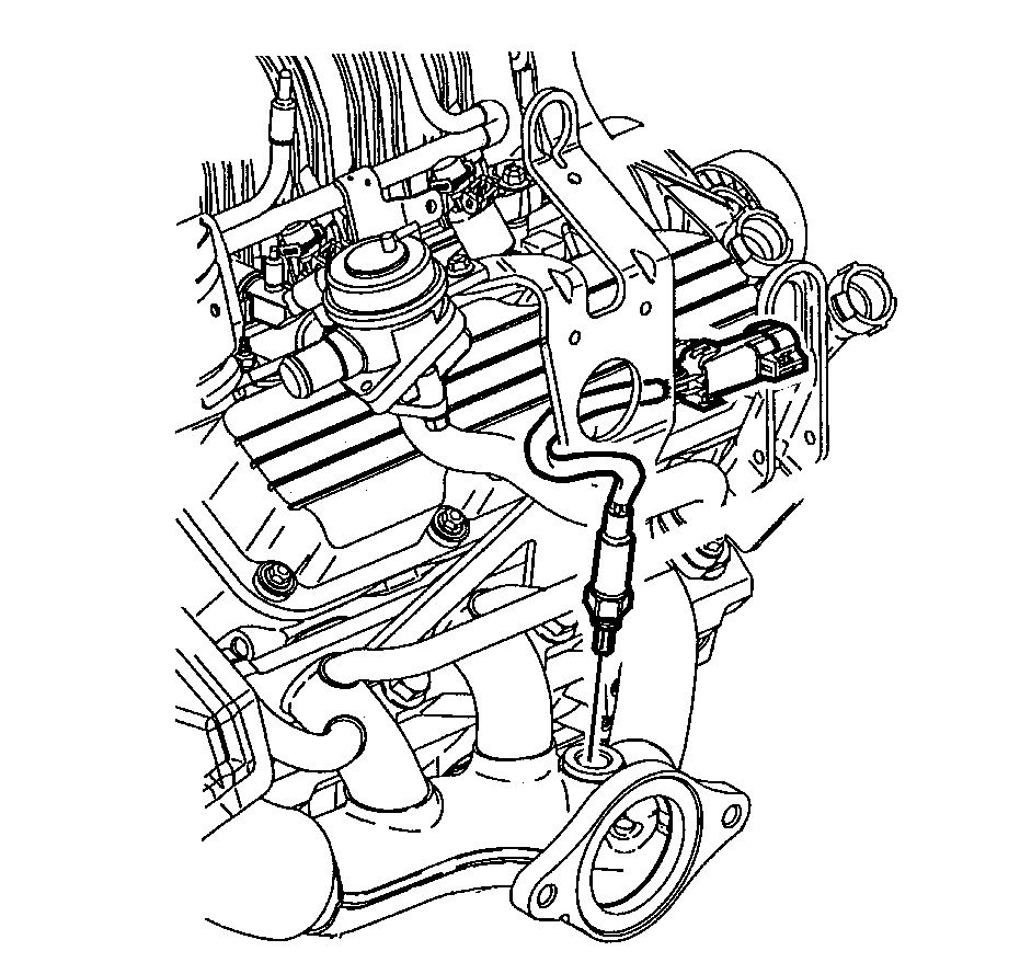
- Coat the threads of the heated oxygen sensor with anti-seize compond GM P/N 5613695, or equivalent.
- Install the heated oxygen sensor.
- Install the heated oxygen sensor lead.
- Install air injection pipe.
- Install air injection pipe assembly nuts.
- Install the EGR mounting bracket.
- Install the EGR mounting bracket bolts.
- Install the EGR inlet pipe to the exhaust manifold.
- Install the EGR inlet pipe bolt.
Notice: Use the correct fastener in the correct location. Replacement fasteners must be the correct part number for that application. Fasteners requiring replacement or fasteners requiring the use of thread locking compound or sealant are identified in the service procedure. Do not use paints, lubricants, or corrosion inhibitors on fasteners or fastener joint surfaces unless specified. These coatings affect fastener torque and joint clamping force and may damage the fastener. Use the correct tightening sequence and specifications when installing fasteners in order to avoid damage to parts and systems.
Tighten
Tighten the right exhaust manifold studs and nuts to 30 N·m
(22 lb ft).
Tighten
Tighten the right side spark plugs to 27 N·m (20 lb ft).
Tighten
Tighten the fuel injector sight shield bracket nuts to 30 N·m
(22 lb ft).
Tighten
Tighten the right engine lift hook nut and bolt to 30 N·m
(22 lb ft).
Tighten
Tighten the air injection check valve bolts to 10 N·m (89 lb in).
Tighten
Tighten the vacuum solenoid bolt to 10 N·m (89 lb in).
Tighten
Tighten the heated oxygen sensor to 42 N·m (31 lb ft).
Tighten
Tighten the air injection pipe nuts to 10 N·m (89 lb in).
Important: Inspect the EGR outlet pipe for leaks during installation. If leaks are present, replace the EGR adapter assembly.
Tighten
Tighten the EGR mounting bracket bolts to 50 N·m (37 lb ft).
Tighten
Tighten the EGR inlet pipe bolt to 29 N·m (21 lb ft).
