Circuit Description
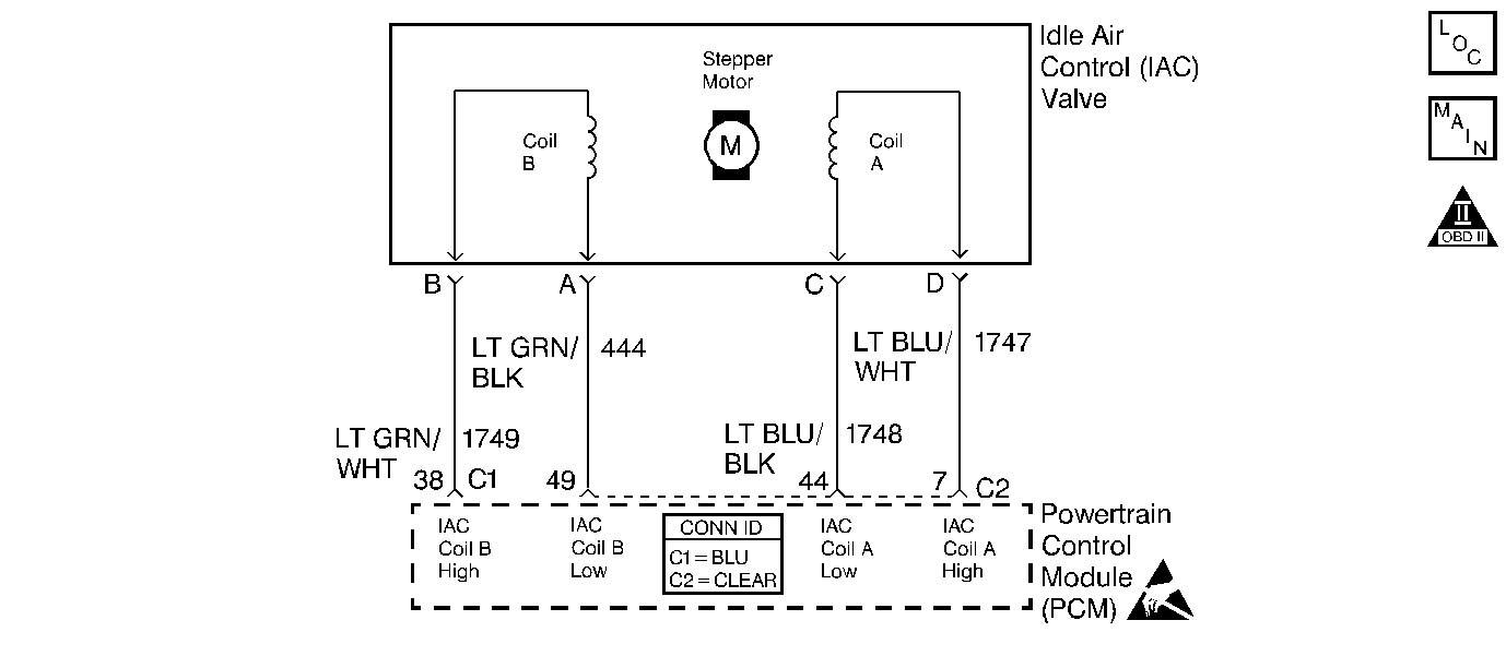
The PCM controls engine idle speed by adjusting the position of the Idle Air Control (IAC) motor pintle. The IAC is a bi-directional motor driven by two coils. The PCM applies current to the IAC coils in steps (counts) to extend the IAC pintle into a passage in the throttle body to decrease air flow. The PCM reverses the current to retract the pintle, increasing air flow. This method allows highly accurate control of idle speed and quick response to changes in engine load. If the PCM detects a condition where too low of an idle speed is present and the PCM is unable to adjust idle speed by increasing the IAC counts, DTC P0506 will set indicating a problem with the idle control system.
Conditions for Running the DTC
| • | No active TP, ECT, MAP, IAT, MAF, CKP, sensor, EVAP, misfire, EGR, VSS, Fuel Trim, injector circuit, DTCs. |
| • | Engine Coolant Temperature is above 70°C (158°F). |
| • | The engine has been running for at least 2 minutes. |
| • | System voltage is between 9.0-16.0 volts. |
| • | Vehicle Speed is less than 3 mph. |
| • | Intake Air Temperature is above -18°C (0°F). |
| • | The throttle is closed |
| • | BARO above 65 kPa. |
| • | Engine run time is greater than 2 minutes. |
Conditions for Setting the DTC
- Engine Speed is 100 RPM or lower than Desired Idle.
- Above condition present for more than 15 seconds.
Action Taken When the DTC Sets
| • | The PCM will illuminate the malfunction indicator lamp (MIL) during the second consecuitive trip in which the diagnostic has been run and failed. |
| • | If equipped with traction control, the PCM will command the EBTCM via the serial data circuit to turn OFF traction control, and the EBTCM will illuminate the TRACTION OFF lamp. |
| • | The PCM will store conditions which were present when the DTC set as Freeze Frame and Failure Records data. |
Conditions for Clearing the MIL/DTC
| • | The PCM will turn OFF the MIL during the third consecutive trip in which the diagnostic has been run and passed. |
| • | The History DTC will clear after 40 consecutive warm-up cycles have occurred without a malfunction. |
| • | The DTC can be cleared by using the scan tool. |
Diagnostic Aids
Check for the following conditions:
| • | Poor connection at PCM or IAC motor. Inspect harness connectors for backed out terminals, improper mating, broken locks, improperly formed or damaged terminals, and poor terminal to wire connection. |
| • | Damaged harness. Inspect the wiring harness for damage. |
| • | Restricted air intake system. Check for a possible collapsed air intake duct, restricted air filter element, or foreign objects blocking the air intake system. |
| • | Throttle body. Check for objects blocking the IAC passage or throttle bore, excessive deposits in the IAC passage and on the IAC pintle, and excessive deposits in the throttle bore and on the throttle plate. |
| • | Large vacuum leak. Check for a condition that causes a large vacuum leak, such as a incorrectly installed or faulty PCV valve or brake booster hose disconnected. |
Refer to Testing for Continuity , Intermittents and Poor Connections Diagnosis , Repairing Connector Terminals , and Connector Repairs .
Reviewing the Fail Records vehicle mileage since the diagnostic test last failed may help determine how often the condition that caused the DTC to be set occurs. This may assist in diagnosing the condition.
Test Description
Number(s) below refer to the step number(s) on the Diagnostic Table:
Step | Action | Value(s) | Yes | No | ||||||||
|---|---|---|---|---|---|---|---|---|---|---|---|---|
1 | Was the Powertrain ON Board Diagnostic System Check performed? | -- | ||||||||||
2 | Are any other DTCs set? | -- | Go to other DTC first | |||||||||
3 |
Does Engine Speed remain within the specified value of Desired Idle for each RPM command? | ±50 RPM | Go to Diagnostic Aids | |||||||||
4 |
Does each light cycle red and green (never OFF)? | -- | ||||||||||
5 |
Was a problem found? | -- | ||||||||||
6 | Visually/physically inspect for the following conditions:
Does any of the above require a repair? | -- | Go to appropriate section for on vehicle service | |||||||||
7 |
Was a problem found? | -- | ||||||||||
8 | Replace IAC valve. Refer to Idle Air Control Valve Replacement . Is the action complete? | -- | -- | |||||||||
9 |
Was a problem found? | -- | ||||||||||
|
Important: : The replacement PCM must be programmed. Refer to Powertrain Control Module Replacement/Programming . Replace the PCM. Is the action complete? | -- | -- | ||||||||||
11 |
Does Engine Speed remain within the specified value of Desired Idle for each RPM command? | ±50 RPM | System OK |
