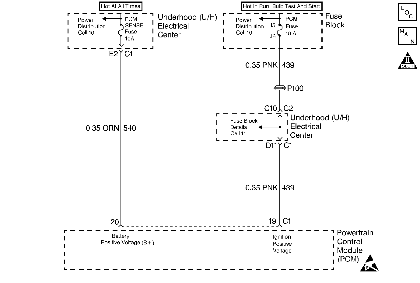
Circuit Description
Circuit 540 is the fused battery feed for the Powertrain Control Module (PCM). Circuit 439 is the ignition feed for the PCM.
When the PCM detects a low voltage, or a high voltage, then DTC P0560 sets. DTC P0560 is a type D DTC.
Conditions for Setting the DTC
| • | The system voltage is low: |
| - | The engine speed is more than 800 RPM. |
| - | The system voltage is less than 10.0 volts for 2 seconds. |
| • | The system voltage is high: |
| - | The transmission temperature is more than 0°C (32°F). |
| - | The system voltage is more than 16.0 volts for 2 seconds. |
Action Taken When the DTC Sets
| • | The transmission defaults to 3rd gear. |
| • | The PCM inhibits TCC operation. |
| • | The transmission defaults to maximum line pressure. |
| • | The PCM disables shift adapts. |
| • | The PCM does not illuminate the Malfunction Indicator Lamp (MIL). |
Conditions for Clearing the DTC
| • | A scan tool can clear the DTC from the PCM history. The PCM clears the DTC from the PCM history if the vehicle completes 40 warm-up cycles without a failure reported. |
| • | The PCM cancels the DTC default actions when the fault no longer exists and the ignition is OFF long enough in order to power down the PCM. |
Diagnostic Aids
| • | Charging the battery with a battery charger could set DTC P0560. Jump starting the vehicle could set DTC P0560. |
| • | If DTC P0560 sets when you operate accessories, inspect the applicable system for poor connections or excessive current draw. |
| • | Inspect the accessory drive belt for wear or incorrect tension. |
Test Description
The numbers below refer to the step numbers on the diagnostic table.
-
The battery voltage must be above 10.5 volts before proceeding with this table.
-
This step ensures that there is no problem with the generator.
-
This step tests for high resistance in the battery feed circuit to the PCM.
Step | Action | Value(s) | Yes | No | ||||||||
|---|---|---|---|---|---|---|---|---|---|---|---|---|
1 | Was the Powertrain On-Board Diagnostic (OBD) System Check performed? | -- | Go to Powertrain On Board Diagnostic (OBD) System Check Powertrain OBD System Check | |||||||||
Important: Before clearing the DTCs, use the scan tool in order to record the Failure Records for reference. The Clear Info function will erase the data. Is the voltage greater than the specified value? | 10.5V | Go to Battery Diagnosis, Section 6. | ||||||||||
Start the engine. Is the Generator/Check Engine lamp illuminated? | -- | Go to Charging System Diagnosis, Section 6. | ||||||||||
4 |
Is the ignition voltage within the specified range? | 13-15V | Go to Charging System Diagnosis, Section 6. | |||||||||
Is the difference between the measured battery voltage and the voltage at terminal 20 greater than the specified value? | 0.5V | |||||||||||
6 | Repair the high resistance in circuit 540. Refer to Troubleshooting Procedures, Section 8. Was a problem found and corrected? | -- | -- | |||||||||
Test circuit 439 for ignition voltage at PCM connector C1-19 with the J 39200 DVOM. Is the difference between the measured battery voltage and the voltage at terminal 19 greater than the specified value? | 0.5V | |||||||||||
8 | Repair the high resistance in circuit 439. Refer to Troubleshooting Procedures, Section 8. Was a problem found and corrected? | -- | -- | |||||||||
9 | Inspect the PCM connector C1 for bent, damaged or backed out connector pins. Did you find and correct a problem? | -- | ||||||||||
10 | Replace the PCM. Refer to Powertrain Control Module Replacement/Programming PCM Replacement/Programming , Section 6. Is the replacement complete? | -- | -- | |||||||||
11 | In order to verify your repair, perform the following procedure:
Has the test run and passed? | -- | System OK |
