For 1990-2009 cars only
- With the index finger and thumb of the left hand circling the synchromesh hub, slide the outer sleeve from the assembly using the right hand. Be careful that the pressure springs do not cause any of the three balls (4) to be ejected and lost.
- Clean the assembly in solvent.
- Inspect the synchromesh hubs (1), outer sleeves, sliding blocks (5) and synchromesh springs (3) for damage.
- Clean the rings in solvent.
- Inspect the synchromesh rings for cracks, deformation and excessive wear.
- Inspect the synchromesh rings for wear by mounting the ring on the respective gear and measuring the gap.
- Inspect positions 1-6. Refer to Synchromesh Ring Specifications .
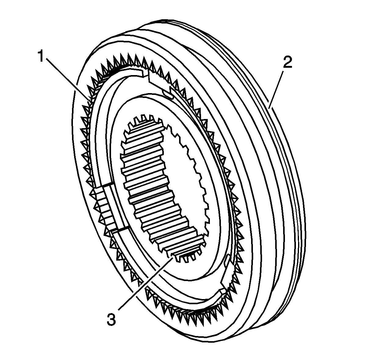
- The 1st/2nd speed synchromesh assembly (2) can be recognized by the larger diameter splined hole in the hub (3), when compared to the 3rd/4th synchromesh assembly. The stepped edge on the outer sleeve is another identification feature (1).
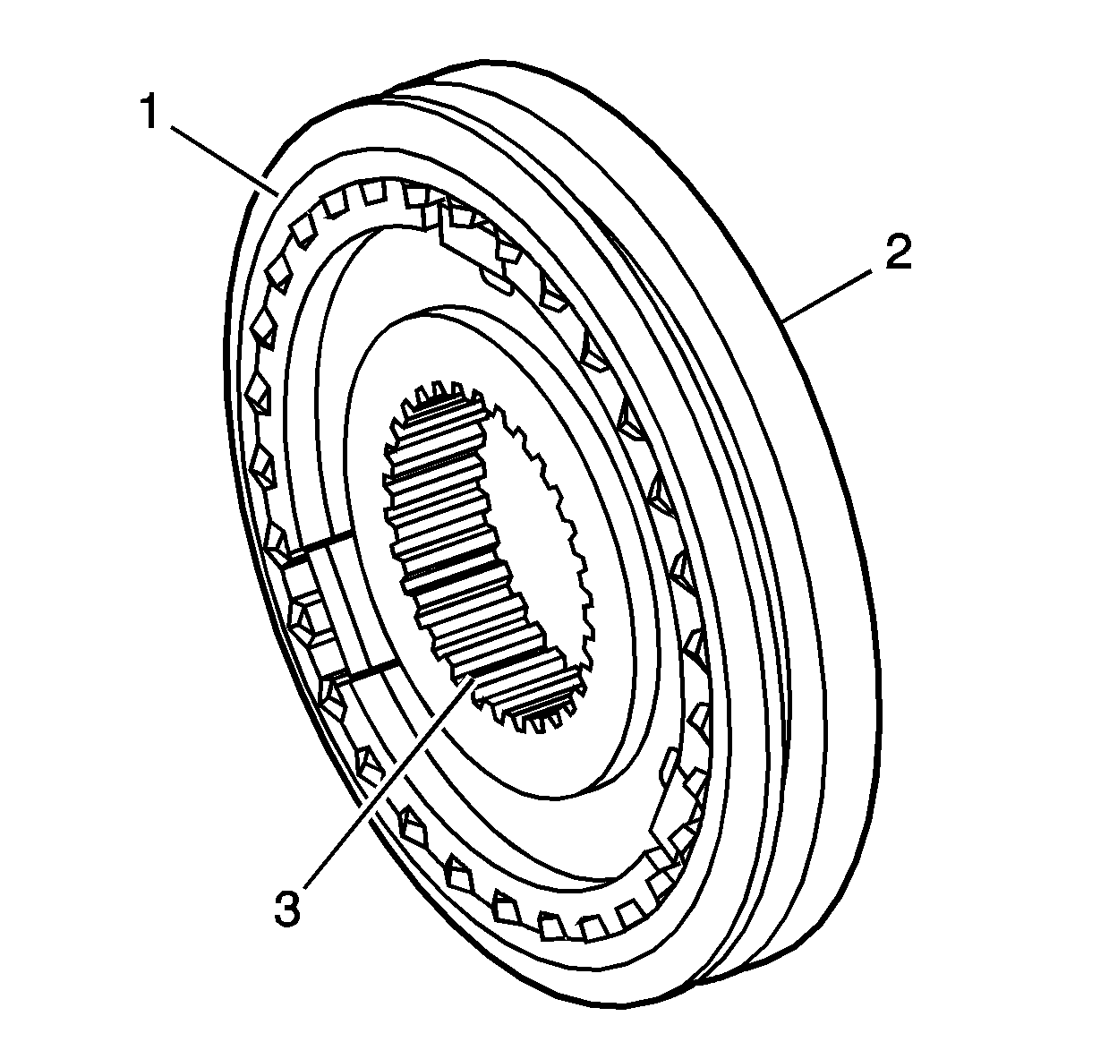
- The 3rd/4th speed synchromesh assembly (2) is identified by the offset selector slot in the outer sleeve (1) and smaller diameter splined hole in the hub (3).
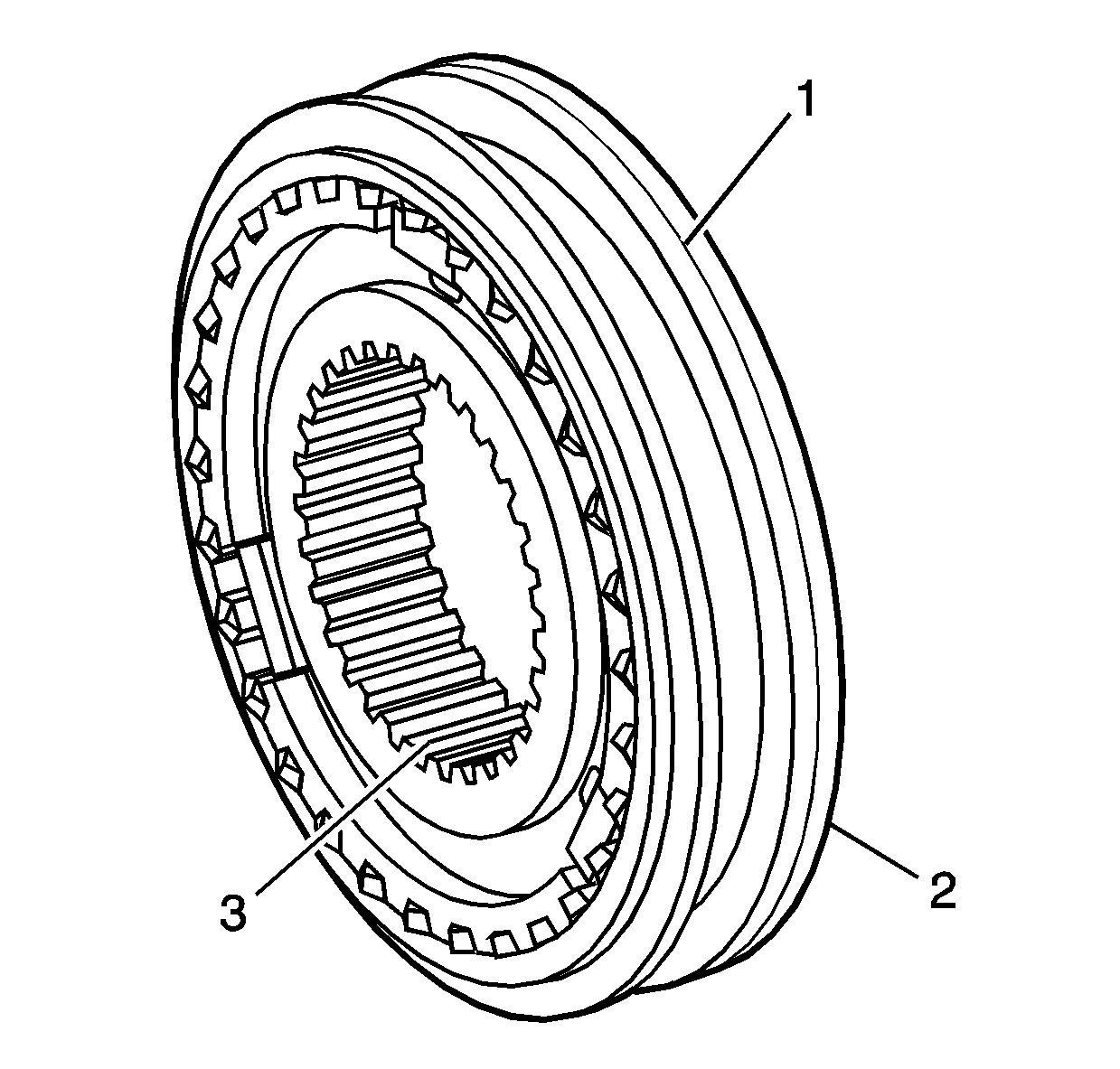
- The 5th/reverse synchromesh assembly (2) is identified by a single groove on the outer sleeve (1) and the larger diameter splined hole in the hub (3), when compared to the 3rd/4th speed synchromesh assembly.
- The synchromesh rings can be identified by the number stamped on the flat face of each one.
- Support the synchromesh hub (1) over a suitable disc to raise it from the bench surface and install the outer sleeve over the hub.
- Insert the sliding keys (5), chamfered ends facing outwards, and springs (3) into each of the locations in the hub. Use Transjel to hold the parts in place.
- Using a small screwdriver, pry each key upwards, just enough to enable a ball (4) to be inserted. While holding the ball inwards, push the key down to capture the ball. Repeat for the remaining two balls.
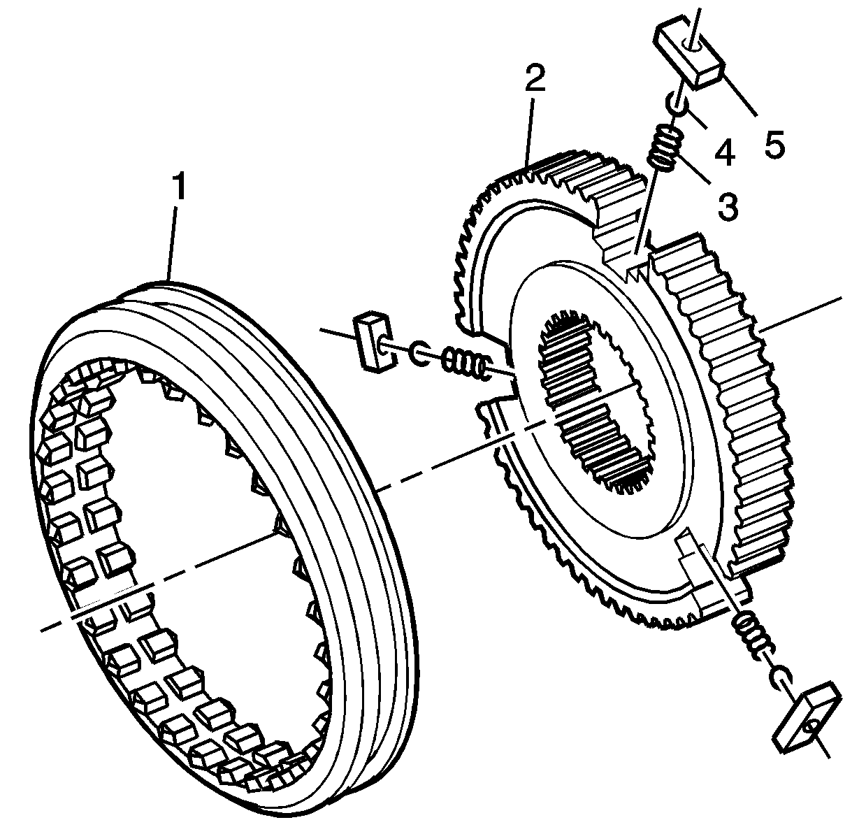
Important: Before disassembling synchronizers, mark the orientation of the outer sleeve to hub.
Important: This is the 1st/2nd synchromesh assembly, the disassembly process is the same for the remaining two assemblies.
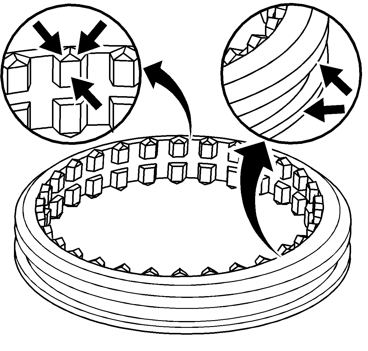
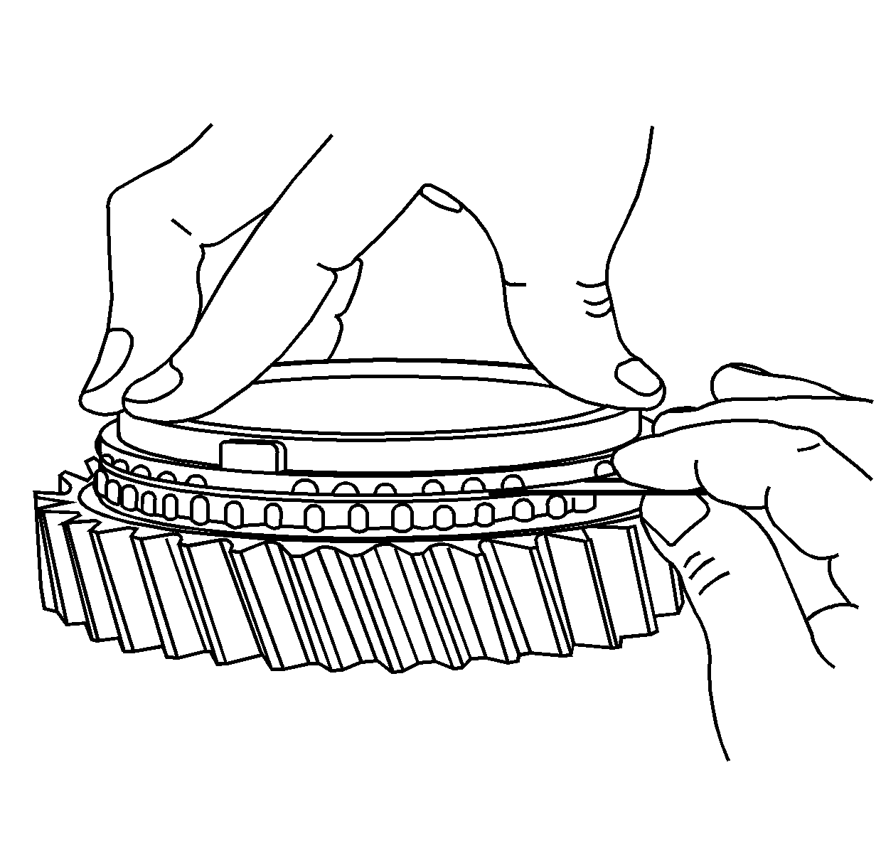
Important: To obtain an accurate measurement, the synchromesh ring must be held squarely and fully installed on its gear. Using feeler gages, measure the gap in at least three places around the circumference. Average the readings and use this figure to assess the synchromesh ring wear.
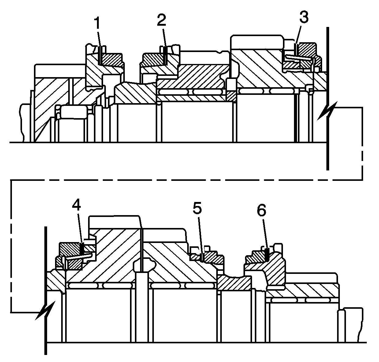
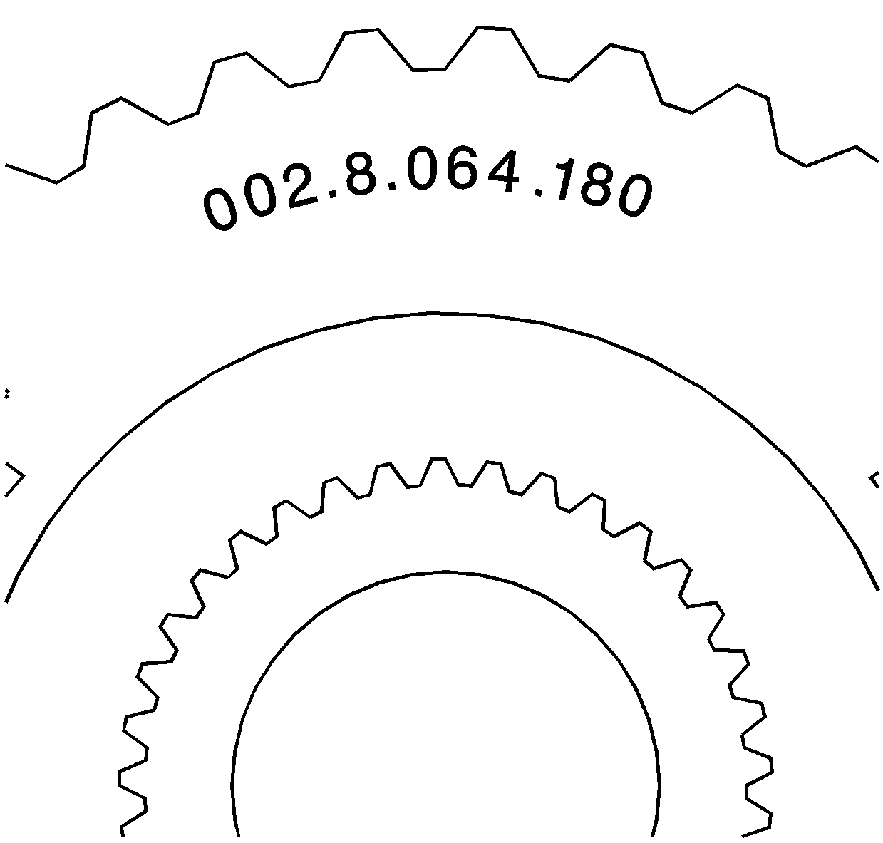
| • | 1st/2nd - 040.8.000.100 |
| • | 3rd/4th - 002.8.064.180 |
| • | 5th/reverse - 011.8.041.180 |

Important: The synchromesh assemblies are to be assembled before pressing onto the mainshaft. Only one synchromesh assembly is described in the following operations, since reassemble is similar for all units.
