Notice:
• Turn the ignition OFF when installing or removing the control module connectors and disconnecting or reconnecting the power to the control module (battery cable, powertrain control module (PCM)/engine control module (ECM)/transaxle control module
(TCM) pigtail, control module fuse, jumper cables, etc.) in order to prevent internal control module damage. • Control module damage may result when the metal case contacts battery voltage. DO NOT contact the control module metal case with battery voltage when servicing a control module, using battery booster cables, or when charging the vehicle battery. • In order to prevent any possible electrostatic discharge damage to the control module, do no touch the connector pins or the soldered components on the circuit board. • Remove any debris from around the control module connector surfaces before servicing the control module. Inspect the control module connector gaskets when diagnosing or replacing the control module. Ensure that the gaskets are installed correctly.
The gaskets prevent contaminant intrusion into the control module. • The replacement control module must be programmed.
Important: It is necessary to record the remaining engine oil life. If the replacement module is not programed with the remaining engine oil life, the engine oil life will default to 100 percent. If the replacement module is not programmed with the remaining engine oil life, the engine oil will need to be changed at 5 000 km (3,000 mi) from the last engine oil change.
Removal Procedure
Service should normally consist of either replacement of the powertrain control module (PCM) or electrically erasable programmable read-only memory (EEPROM) re-programming.
If the diagnostic procedures call for the PCM to be replaced, the PCM should be inspected first in order to verify the PCM is the correct part. DTC P0602 indicates the EEPROM programming has malfunctioned. When DTC P0602 is set, re-program the EEPROM.
- Using a scan tool, retrieve the percentage of remaining engine oil. Record the remaining engine oil life.
- Disconnect the negative battery cable. Refer to Battery Negative Cable Disconnection and Connection in Engine Electrical.
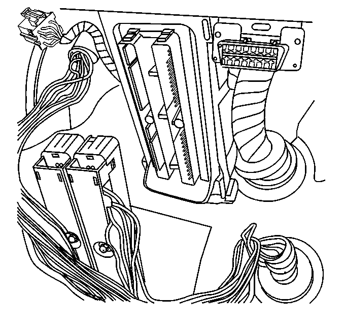
- Remove the left closeout/insulator panel. Refer to Instrument Panel Insulator Panel Replacement - Left Side in Instrument Panel, Gages, and Console.
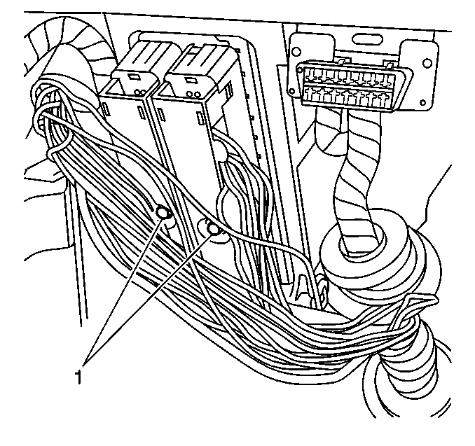
- Loosen the PCM connector screws (1).
- Disconnect the PCM electrical connectors.
- Depress the PCM retaining tabs.
- Slide the PCM from the PCM bracket.
Caution: Unless directed otherwise, the ignition and start switch must be in the OFF or LOCK position, and all electrical loads must be OFF before servicing any electrical component. Disconnect the negative battery cable to prevent an electrical spark should a tool or equipment come in contact with an exposed electrical terminal. Failure to follow these precautions may result in personal injury and/or damage to the vehicle or its components.
Notice: Do not touch the PCM connector pins or soldered components on the circuit board in order to prevent possible electrostatic discharge (ESD) damage. Do not remove the integrated circuit boards from the carrier.
Installation Procedure
Remove the new PCM from the packaging and inspect the service number to verify the number is the same number, or an updated number, as the faulty PCM.
- Slide the PCM into the PCM bracket.
- Install the PCM electrical connectors.
- Tighten the PCM connector screws (1).
- Install the left closeout/insulator panel. Refer to Instrument Panel Insulator Panel Replacement - Left Side in Instrument Panel, Gages, and Console.
- Connect the negative battery cable. Refer to Battery Negative Cable Disconnection and Connection in Engine Electrical.
- Program the PCM. Refer to Control Module References in Computer/Integrating Systems.
- The replacement PCM will NOT allow secondary air injection (AIR) pump operation until a total of 10 miles have accumulated.
Notice: Do not touch the PCM connector pins or soldered components on the circuit board in order to prevent possible electrostatic discharge (ESD) damage. Do not remove the integrated circuit boards from the carrier.
Notice: Refer to Fastener Notice in the Preface section.
Tighten
Tighten the PCM connector screws to 8 N·m (71 lb in).
Important:: The replacement PCM must be reprogrammed and the crankshaft position (CKP) system variation learn procedure must be performed.
