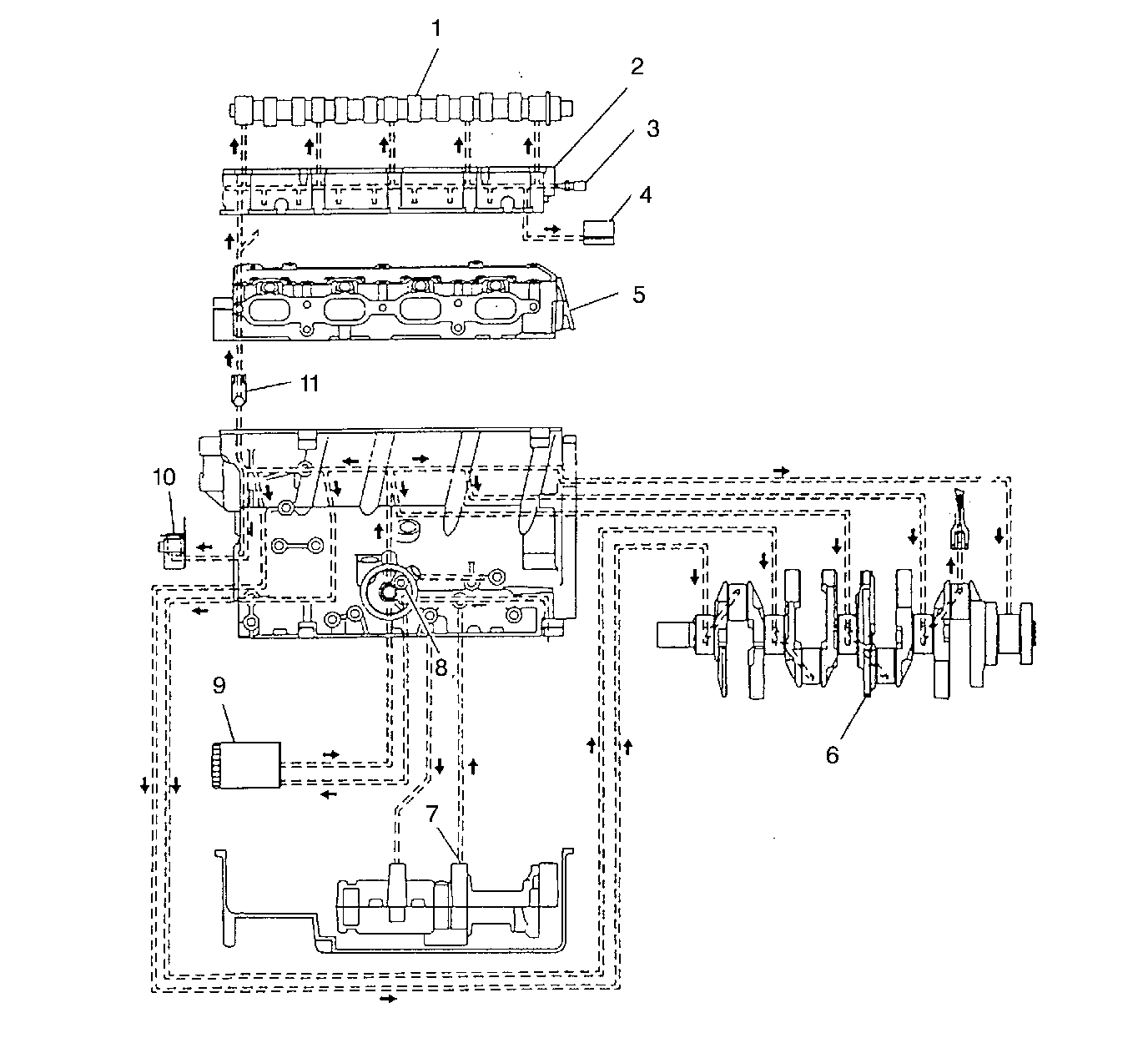
Oil Flow Diagram

Oil is applied under pressure to the crankshaft, connecting rods, balance shaft assembly, camshaft bearing surfaces, valve lifters and timing chain hydraulic tensioner. All other moving parts are lubricated by gravity flow or splash.
Oil enters the gerotor type oil pump (7) thorough a fixed inlet screen. The oil pump is driven by one of the balance shafts. The oil pump body and the cover are cast aluminum, and the gerotor gears are steel. The pressurized oil from the pump passes through the oil filter (9). The oil filter is located on the left (front) side of the engine block. A by-pass valve (8) in the engine block allows continuous oil flow in case the oil filter should become restricted. Oil then enters the gallery where it is distributed to the balance shafts, the crankshaft (6), the timing chain hydraulic tensioner (10), the lifters (4) and the camshafts (1). The connecting rod bearings are oiled by constant oil flow passages through the crankshaft connecting the main journals to the rod journals. A groove around each main bearing furnishes oil to the drilled crankshaft passages. An oil cooling hole, which indexes once each revolution with the connecting rod oil feed hole, is drilled in the connecting bearing surface. The pressurized oil passages through the oil flow check valve (11) into the cylinder head (5) and then into each camshaft housing (2). Cast passages feed each valve lifter (4) and drilled passages feed each camshaft bearing surface. An engine oil pressure switch or sensor (3) is installed at the end of the intake camshaft housing oil gallery. Oil returns to the oil pan through passages cast into the camshaft housings and the cylinder head. The timing chain housing drains directly into the oil pan.
