Refer to Engine Controls Schematic
Power, Ground, KS,CMP,CKP,Coils, and ICM
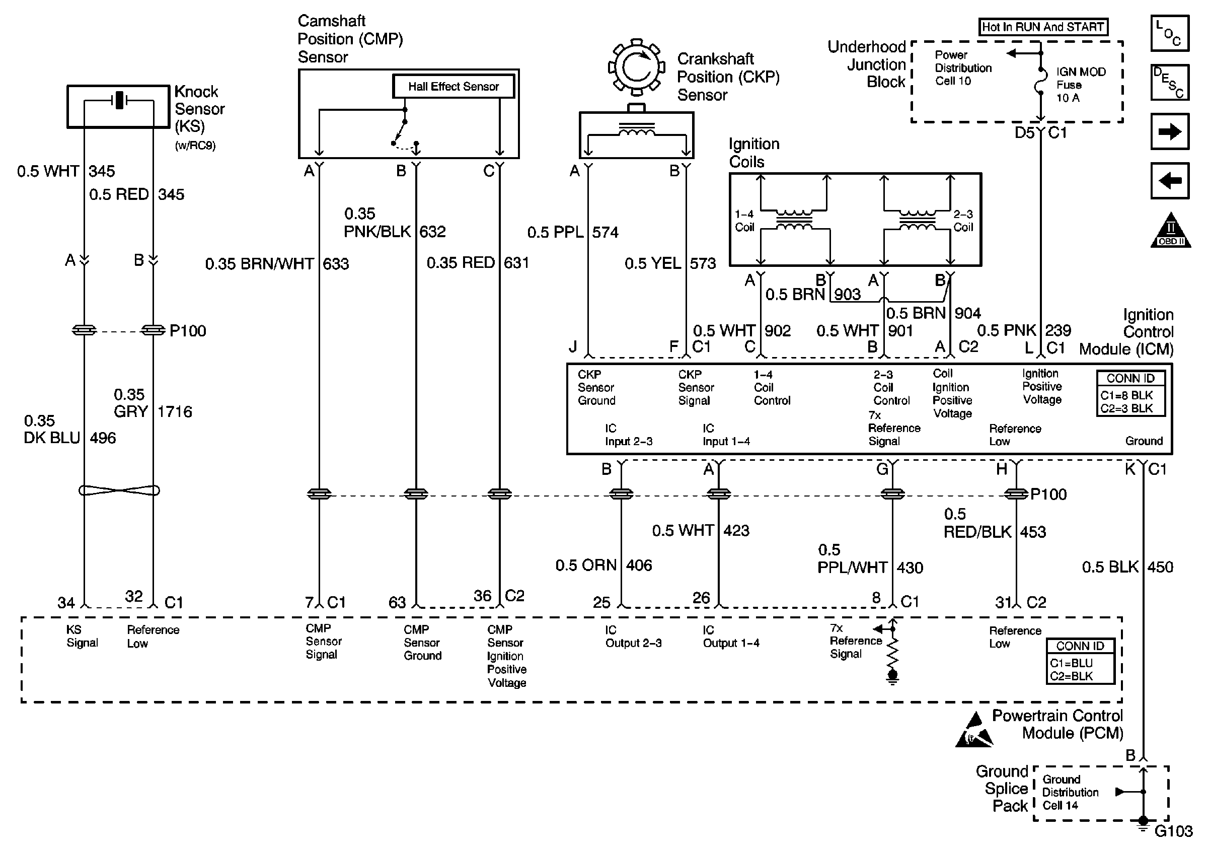
.
Circuit Description
This engine is equipped with a ignition system called the electronic ignition (EI) system. The primary circuit of the EI system consists of the following components:
| • | Two separate ignition coils |
| • | The electronic ignition control module (ICM) |
| • | The crankshaft position (CKP) sensor |
| • | The related connecting wires and the ignition control portion of the PCM |
Each secondary circuit consists of the following components:
| • | The secondary winding of the coil |
| • | The 2 connecting metal strips molded into the coil housing |
| • | The spark plug boot/connector assemblies |
| • | The spark plugs |
Diagnostic Aids
| • | A small amount of resistance in the battery positive voltage circuit to the PCM may cause a no-start. Test the B+ circuit for excessive resistance or corrosion. Refer to Wiring Repairs in Wiring Systems. |
| • | The PCM grounds will cause a no-start only if all of the grounds are not making a good connection. Refer to Testing for Intermittent Conditions and Poor Connections in Wiring Systems. |
| • | Inspect the throttle position (TP) sensor for the following conditions: |
| - | Any binding or sticking |
| - | An intermittent short |
| - | An intermittent open |
| • | The engine coolant temperature (ECT) sensor may be skewed within specifications and not set a code. On a cold vehicle the ECT and intake air temperature (IAT) should be within 3°C (5°F) of each other. For a hot vehicle, let the engine cool to the ambient temperature before performing the test. |
| • | The manifold absolute pressure (MAP) sensor may be skewed within specifications and not set a code. Refer to DTC P0105 Manifold Absolute Pressure (MAP) Sensor Performance/Range . |
| • | A loose crankshaft position (CKP) sensor may cause an intermittent no-start condition by moving away from the reluctor wheel. Verify that the sensor and the mating surface are clean and tight. |
Test Description
The numbers below refer to the step numbers on the diagnostic table.
-
Verify that the fuel pump runs by removing the fuel cap and listening, or by feeling the fuel rail or fuel lines on key up.
-
Repair the cause of the malfunctioning Spark plugs before replacing.
-
Inspect for basic engine malfunction like low compression, burnt valves, worn timing chain and gears, etc.
-
A short to voltage in this step will read as a negative resistance.
-
Any time the CKP sensor is removed the Crankshaft Position Variation learn procedure must be performed.
-
The replacement PCM must be reprogrammed and the Crankshaft Position Variation learn procedure must be performed.
Step | Action | Values | Yes | No | ||||||||||
|---|---|---|---|---|---|---|---|---|---|---|---|---|---|---|
1 | Did you perform the Powertrain On Board Diagnostic (OBD) System Check? | -- | Go to Step 2 | |||||||||||
2 | Are DTCs P0601, P0602 or 1629 set? | -- | Go to Step 3 | |||||||||||
3 |
Does the CKP Activity Counter increment? | -- | Go to Step 4 | Go to Step 9 | ||||||||||
Does the fuel pump run? | -- | Go to Step 5 | ||||||||||||
5 |
Caution: Wrap a shop towel around the fuel pressure connection in order to reduce the risk of fire and personal injury. The towel will absorb any fuel leakage that occurs during the connection of the fuel pressure gage. Place the towel in an approved container when the connection of the fuel pressure gage is complete. Does the fuel gauge read within the specified value? | 358-405 kPa (52-58 psi) | Go to Step 6 | Go to Fuel System Diagnosis | ||||||||||
6 |
Important:: Not grounding the ICM Assembly, may cause erratic spark. Does the spark tester spark on all cylinders? | -- | Go to Step 7 | Go to Step 15 | ||||||||||
Did you find and correct the condition? | -- | Go to Step 32 | Go to Step 8 | |||||||||||
Inspect for basic engine problems. Refer to Base Engine Misfire Diagnosis in Engine Mechanical. Did you find and correct any conditions? | -- | Go to Step 32 | Go to Step 27 | |||||||||||
9 |
Does the DMM read the specified value? | B+ | Go to Step 10 | Go to Step 23 | ||||||||||
10 | Connect the DMM between battery ground and the CKP sensor ground circuit at the connector. Does the DMM read voltage? | -- | Go to Step 25 | Go to Step 11 | ||||||||||
11 | With the DMM measure the resistance between the battery ground and the CKP sensor ground circuit at the connector. Does the DMM read infinity? | -- | Go to Step 12 | Go to Step 26 | ||||||||||
12 | With the DMM measure the resistance between the CKP sensor ground circuit and the CKP sensor signal circuit at the connector. Does the DMM read within the specified value. | 500 - 900 ohms | Go to Step 13 | Go to Step 18 | ||||||||||
13 |
Does the DMM read more then the specified value? | 200 mV | Go to Step 14 | Go to Step 28 | ||||||||||
14 |
Does the CKP Activity Counter increment? | -- | Go to Step 19 | Go to Step 22 | ||||||||||
15 |
Does the DMM read B+? | -- | Go to Step 16 | Go to Step 19 | ||||||||||
16 |
Does the test lamp blink? | -- | Go to Step 24 | Go to Step 17 | ||||||||||
17 |
Important:: DO NOT use a test lamp in the next test. Does the DMM read the specified value? | B+ | Go to Step 21 | Go to Step 20 | ||||||||||
18 |
Did you find and correct the condition? | -- | Go to Step 32 | Go to Step 28 | ||||||||||
19 |
Did you find and correct the condition? | -- | Go to Step 32 | Go to Step 29 | ||||||||||
20 |
Did you find and correct the condition? | -- | Go to Step 32 | Go to Step 31 | ||||||||||
21 |
Did you find and correct the condition? | -- | Go to Step 32 | Go to Step 29 | ||||||||||
Did you find and correct the condition? | -- | Go to Step 32 | Go to Step 31 | |||||||||||
23 | Repair open in the ICM ground circuit and/or ignition feed circuit. Refer to Wiring Repairs in Wiring Systems. Did you complete the repair? | -- | Go to Step 32 | -- | ||||||||||
24 | Repair open or short to ground in the Jumper Harness between the ICM and the Coils. Refer to Wiring Repairs in Wiring Systems. Did you complete the repair? | -- | Go to Step 32 | Go to Step 30 | ||||||||||
25 | Repair the short to voltage in the CKP sensor circuit. Refer to Wiring Repairs in Wiring Systems. Did you complete the repair? | -- | Go to Step 32 | -- | ||||||||||
26 | Repair the short to ground in the CKP sensor circuit. Refer to Wiring Repairs in Wiring Systems. Did you complete the repair? | -- | Go to Step 32 | -- | ||||||||||
27 |
Did you find and correct the condition? | -- | Go to Step 32 | -- | ||||||||||
|
Important:: The Crankshaft Position Variation procedure must be performed. Refer to Crankshaft Position System Variation Learn . Replace the CKP sensor. Refer to Crankshaft Position Sensor Replacement . Did you complete the replacement? | -- | Go to Step 32 | -- | |||||||||||
29 | Replace the ICM. Refer to Ignition Control Module Replacement . Did you complete the replacement? | -- | Go to Step 32 | -- | ||||||||||
30 | Replace both Ignition Coils. Refer to Ignition Coil Replacement . Did you complete the replacement? | -- | Go to Step 32 | -- | ||||||||||
|
Important:: The replacement PCM must be programmed. Refer to Powertrain Control Module Replacement/Programming . Replace the PCM. Refer to Powertrain Control Module Replacement . Did you complete the replacement? | -- | Go to Step 32 | -- | |||||||||||
32 | Attempt to start the engine. Does the engine start and continue to run? | -- | Go to Step 2 |
