For 1990-2009 cars only
Removal Procedure
- Disconnect the negative battery cable. Refer to Battery Negative Cable Disconnection and Connection .
- Remove the air cleaner assembly. Refer to Air Cleaner Outlet Duct Replacement .
- Disconnect the clutch actuator line from the clutch actuator.
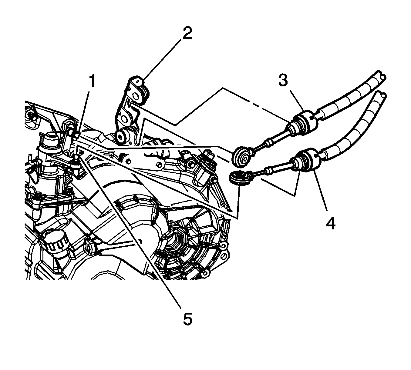
- Disconnect the select cable (3) from the transaxle select lever (1).
- Disconnect the shift cable (4) from the transaxle shift lever (5).
- Remove both cables from the cable bracket (2).
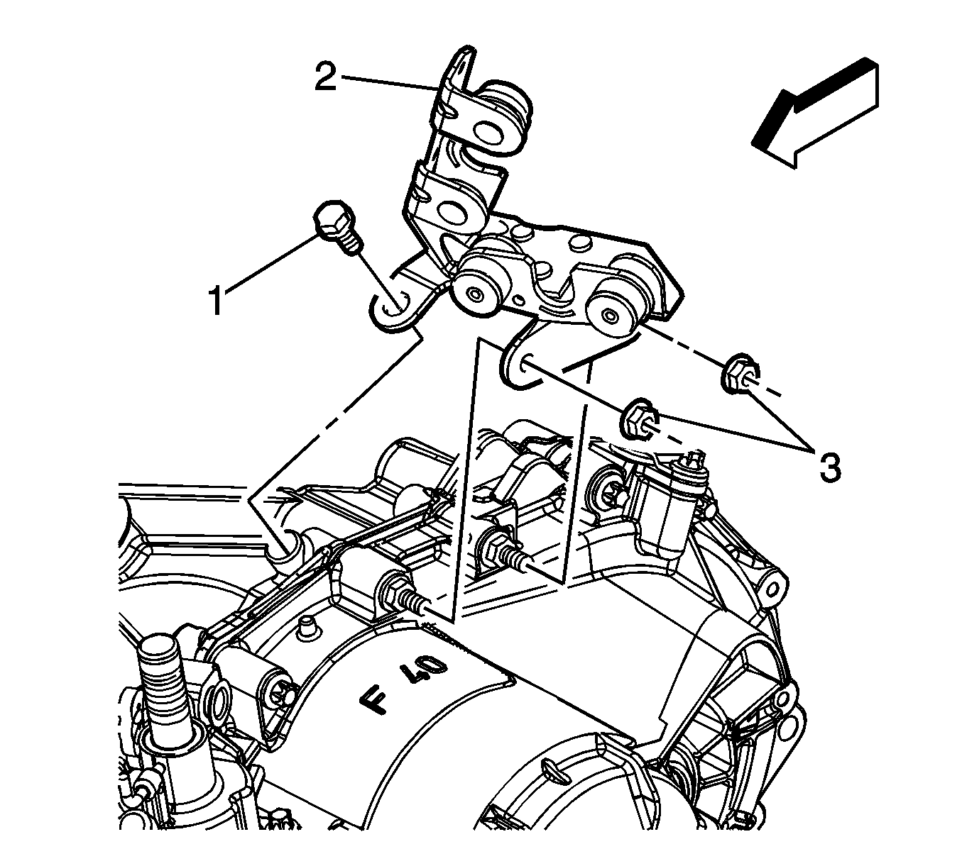
- Remove the cable bracket bolt (1) and nuts (3).
- Remove the cable bracket (2).
- Disconnect the vehicle speed sensor (VSS) electrical connector and position the harness out of the way.
- Disconnect the backup lamp switch electrical connector and position the harness out of the way.
- Tie the radiator to the upper hood latch panel.
- Install the engine support fixture. Refer to Engine Support Fixture .
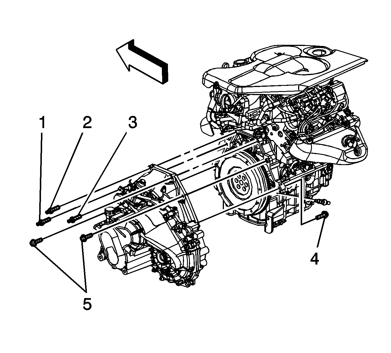
- Remove the upper transaxle mounting studs (1-3) and bolt (5).
- Raise and support the vehicle. Refer to Lifting and Jacking the Vehicle .
- Remove the front wheels and tires. Refer to Tire and Wheel Removal and Installation .
- Remove the left engine splash shield. Refer to Engine Splash Shield Replacement - Left Side .
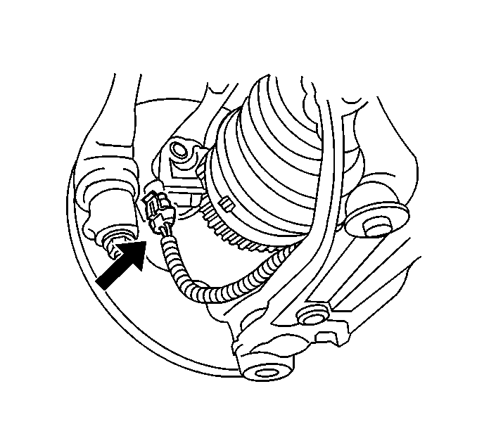
- Disconnect the 2 front wheel speed sensor connectors.
- Unclip the wheel speed sensor wire harness and position the harness out of the way.
- Remove the frame. Refer to Frame Replacement .
- Remove the starter. Refer to Starter Motor Replacement .
- Remove the transaxle front mount from the transaxle. Refer to Transmission Front Mount Replacement .
- Remove the transaxle rear mount from the transaxle. Refer to Transmission Rear Mount Replacement .
- Remove the wheel driveshaft from the vehicle. Refer to Wheel Drive Shaft Replacement .
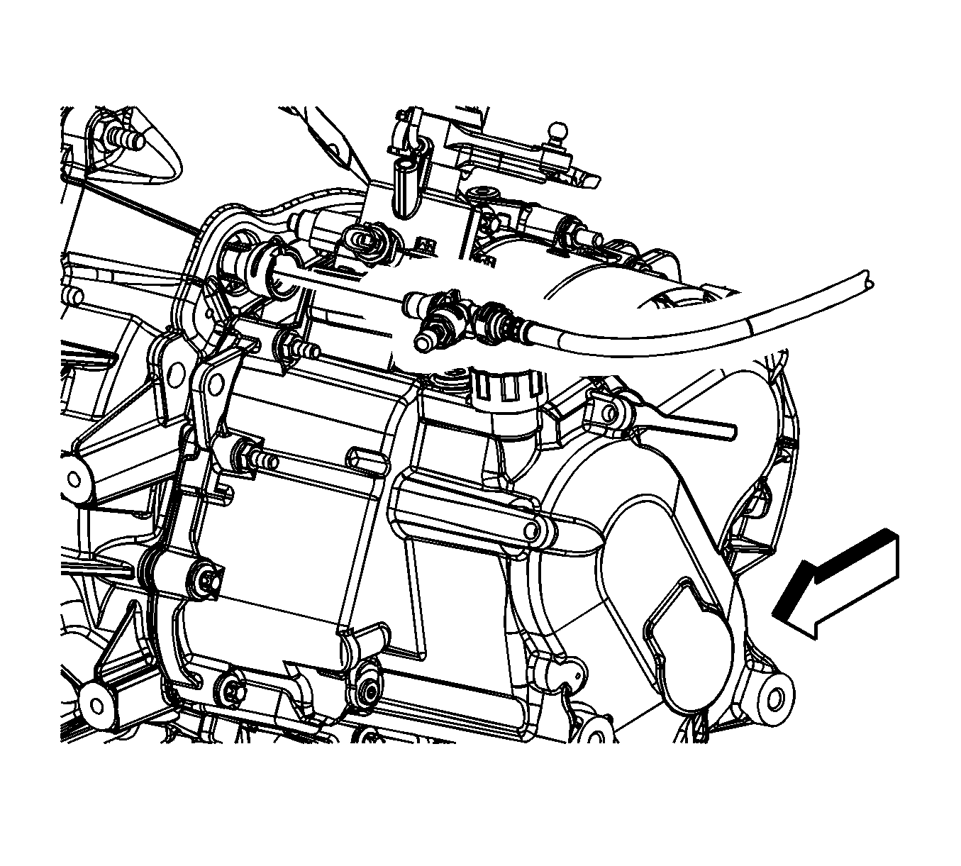
- Lower the engine and transaxle assembly with the engine support fixture enough to clear the left side inner body panel.
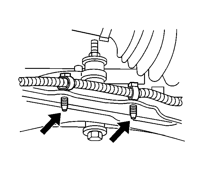
- Remove the front transaxle brace bolts (1).
- Remove the front transaxle brace (2).
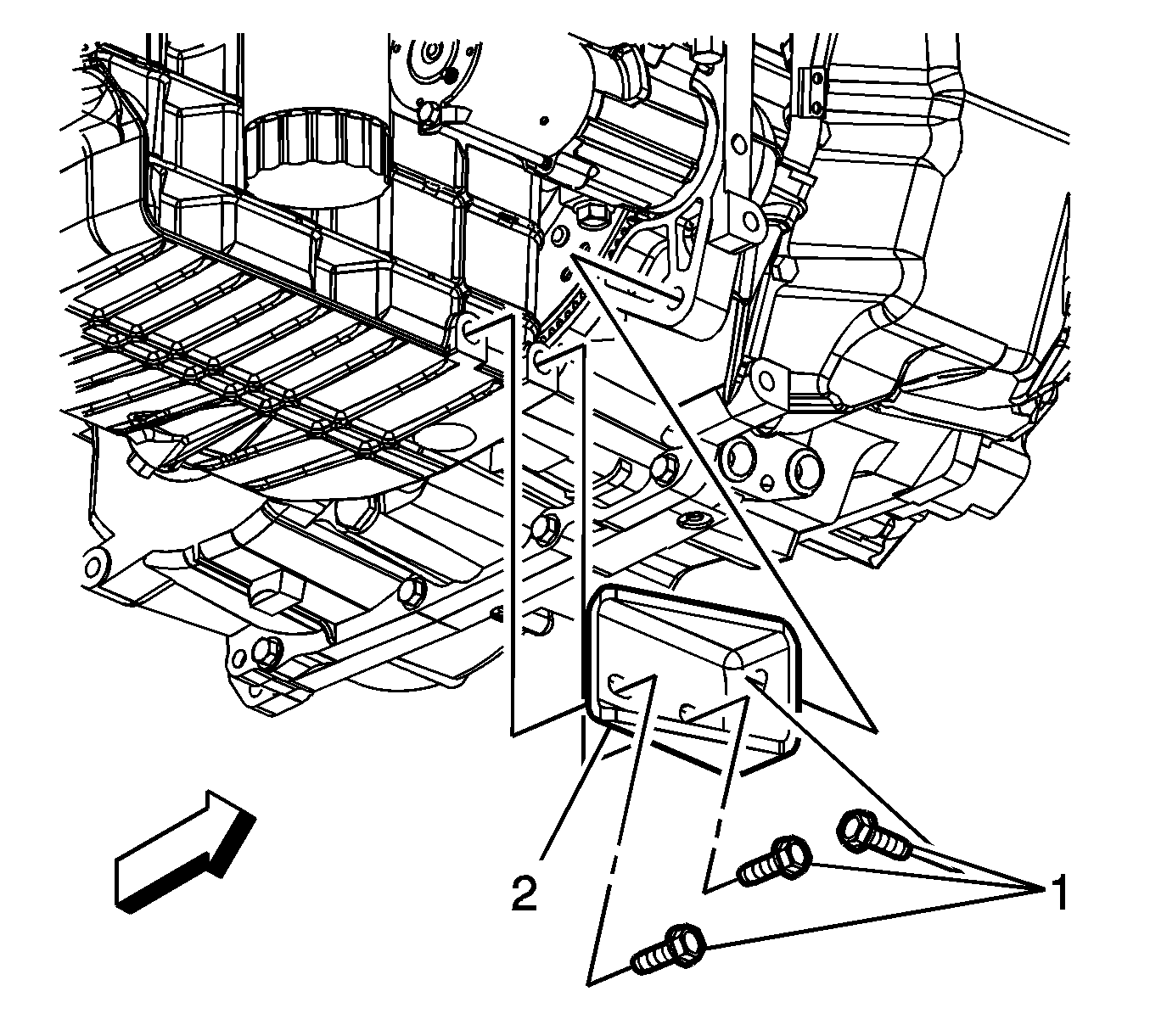
- Remove the rear transaxle brace bolt (2).
- Remove the lower transaxle mounting bolts (4, 5).
- Support and remove the transaxle from the vehicle.
Installation Procedure
- Support and raise the transaxle into the vehicle.
- Install the lower transaxle mounting bolts. Hand tighten only.
- Lower the vehicle.
- Install the upper transaxle mounting bolts. Hand tighten only.
- Secure bolts (1, 4) in 2 steps.
- Tighten both bolts to 10 N·m (89 lb in).
- Tighten both bolts to 60 N·m (44 lb ft).
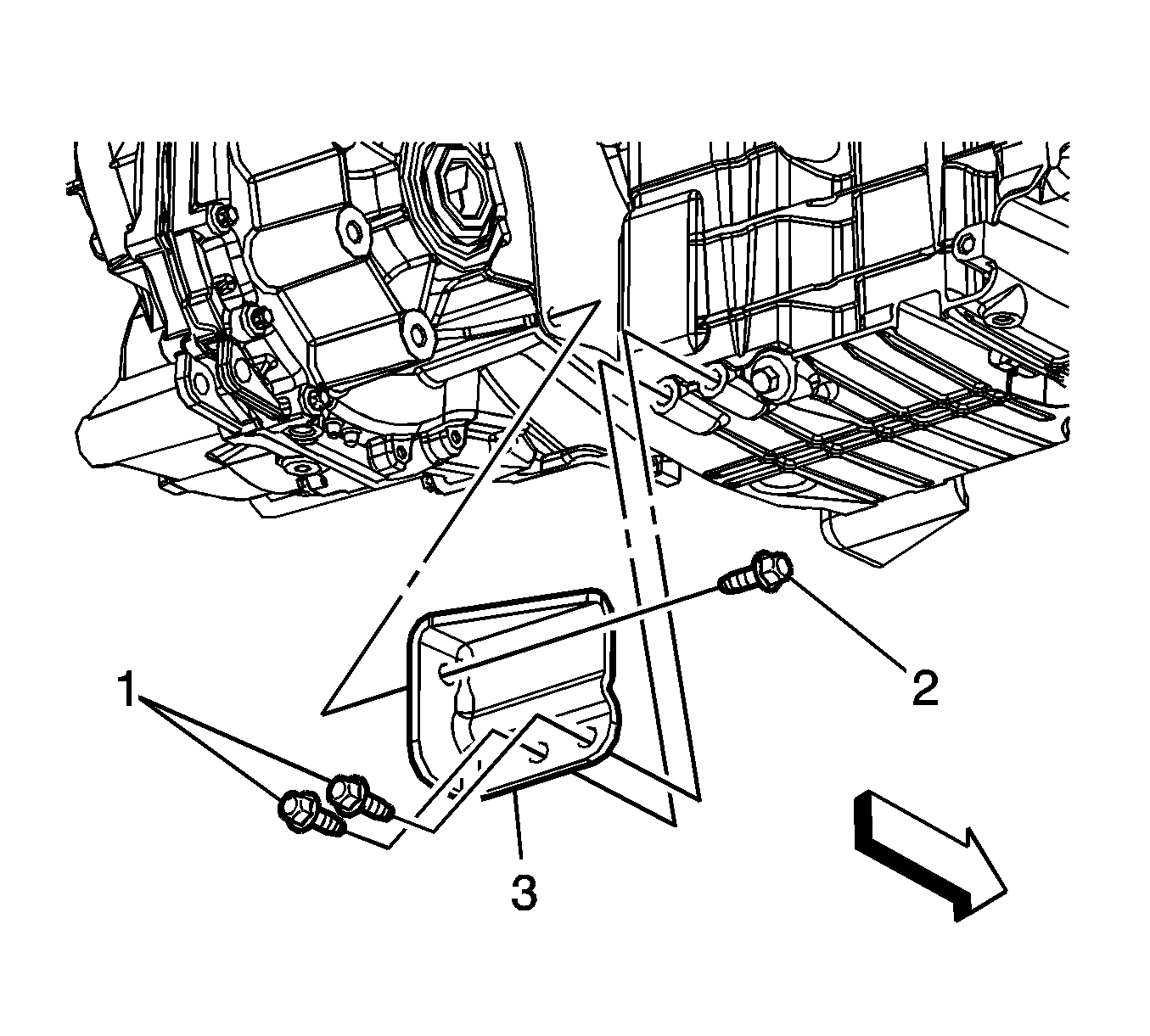
- Secure the remaining bolts (2, 3, 5).
- Install the rear transaxle brace bolt (2).
- Install the front transaxle brace (2).
- Install the front transaxle brace bolts (1).
- Raise the engine and transaxle assembly with the engine support fixture into position.
- Install the wheel driveshaft to the vehicle. Refer to Wheel Drive Shaft Replacement .
- Install the transaxle front mount to the transaxle. Refer to Transmission Front Mount Replacement .
- Install the transaxle rear mount to the transaxle. Refer to Transmission Rear Mount Replacement .
- Install the starter. Refer to Starter Motor Replacement .
- Install the frame. Refer to Frame Replacement .
- Route the wheel speed sensor wire harness to the speed sensor.
- Connect the wheel speed sensor electrical connectors.
- Install the left engine splash shield. Refer to Engine Splash Shield Replacement - Left Side .
- Install the front wheels and tires. Refer to Tire and Wheel Removal and Installation .
- Lower the vehicle.
- Remove the engine support fixture.
- Connect the backup lamp switch electrical connector.
- Connect the VSS electrical connector.
- Install the cable bracket (2).
- Install the cable bracket bolt (1).
- Install the cable bracket nuts (3).
- Install both cables into the cable bracket (2).
- Connect the shift cable (4) to the transaxle shift lever (5).
- Connect the select cable (3) to the transaxle select lever (1).
- Connect the clutch actuator line to the clutch actuator.
- Install the air cleaner assembly. Refer to Air Cleaner Outlet Duct Replacement .
- Connect the negative battery cable. Refer to Battery Negative Cable Disconnection and Connection .
Notice: Refer to Fastener Notice in the Preface section.
Tighten
Tighten
Tighten the remaining bolts to 60 N·m (44 lb ft).
Tighten
Tighten the bolt to 30 N·m (22 lb ft).
Tighten
Tighten the bolts to 50 N·m (37 lb ft).
Tighten
Tighten the bolt to 25 N·m (18 lb ft).
Tighten
Tighten the nut to 25 N·m (18 lb ft).
