For 1990-2009 cars only
Tools Required
J 36850 Transjel Lubricant
Removal Procedure
- Remove the air cleaner outlet duct. Refer to Air Cleaner Outlet Duct Replacement .
- Remove the battery. Refer to Battery Replacement .
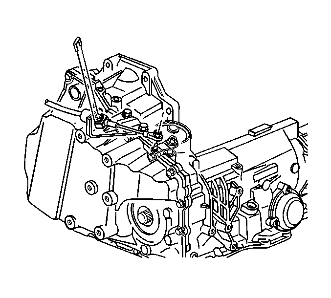
- Remove the shift cable from the transaxle range selector.
- Remove the transaxle shift cable bracket bolts and the bracket from the transaxle.
- Disconnect the transaxle wiring harness connector.
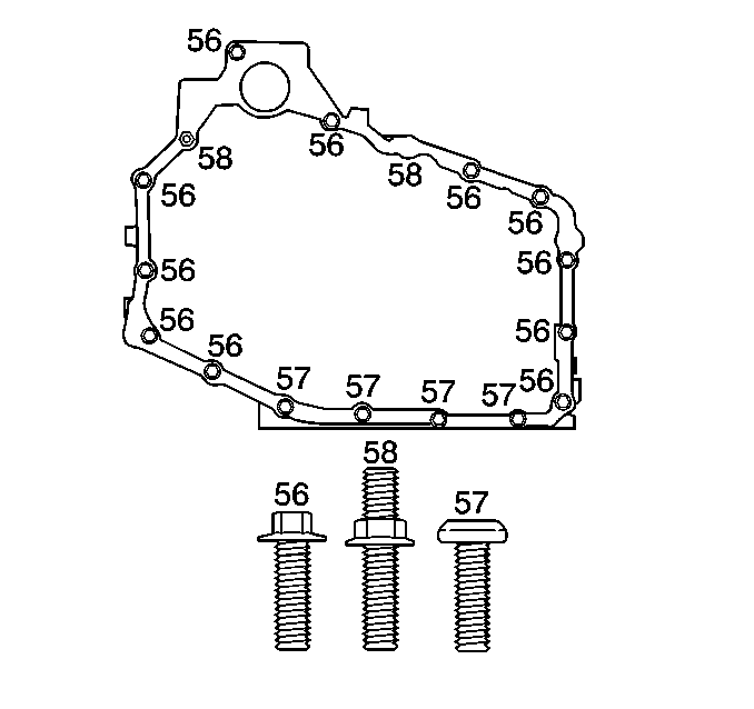
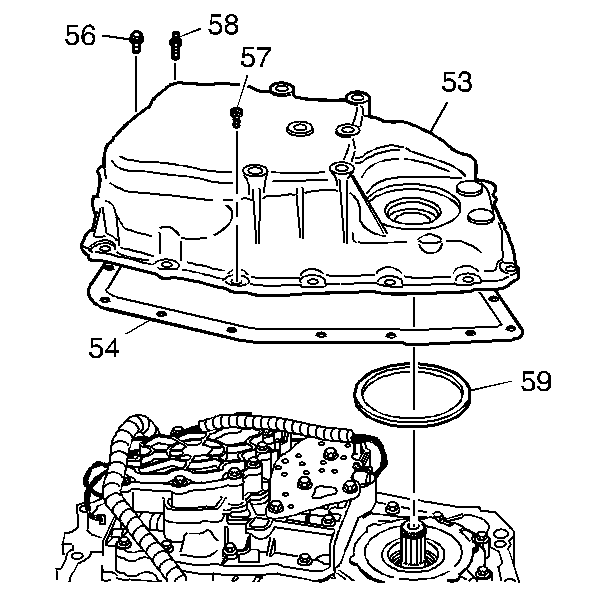
- Remove top side cover bolt (56, 58).
- Install the engine support fixture. Refer to Engine Support Fixture .
- Raise and support the vehicle. Refer to Lifting and Jacking the Vehicle .
- Remove the left front wheel. Refer to Tire and Wheel Removal and Installation .
- Remove the left engine splash shield. Refer to Engine Splash Shield Replacement - Left Side .
- Remove the wheel speed sensor harness from retainers on lower control arm.
- Remove the left transaxle mount. Refer to Transmission Mount Replacement - Left Side .
- Remove the front cradle to radiator support brackets on each side.
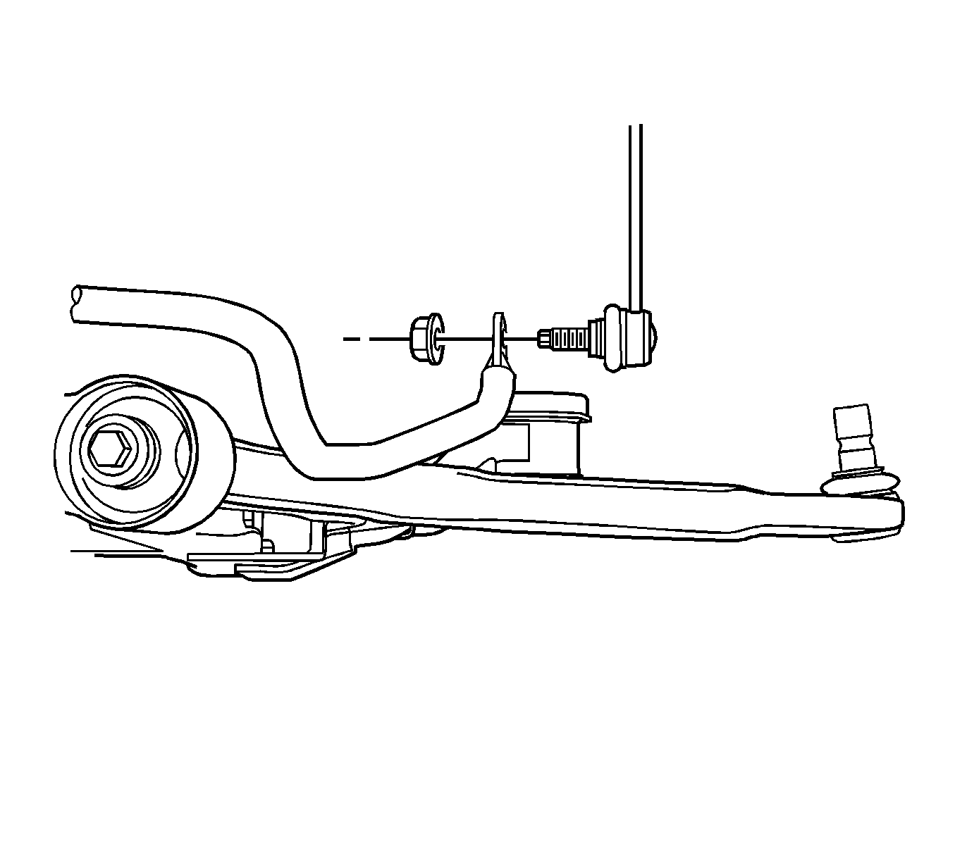
- Remove both stabilizer links from the stabilizer and reposition stabilizer to access steering gear- to-frame bolts. Refer to Stabilizer Shaft Link Replacement .
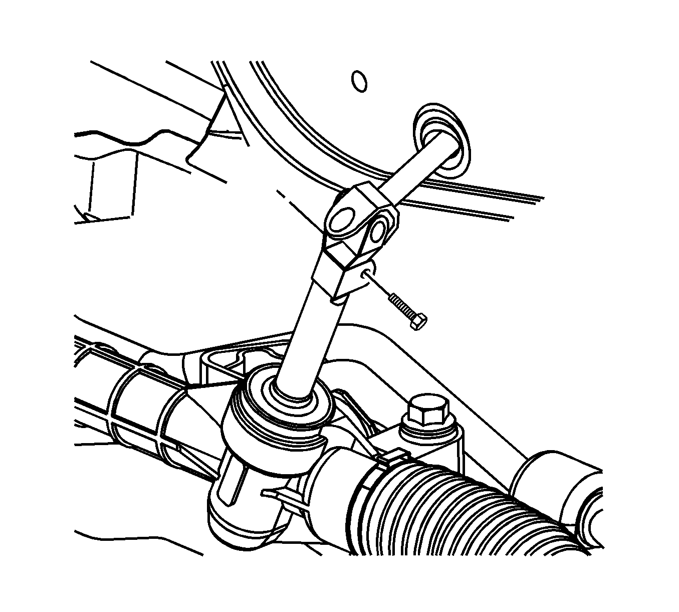
- Remove the intermediate shaft to steering gear pinch bolt. Refer to Steering Gear Replacement .
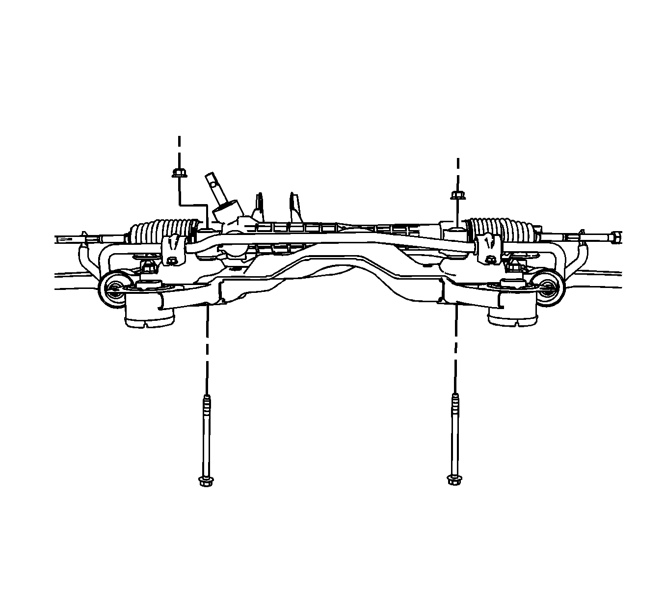
- Remove steering gear-to-frame bolts and support steering gear. Refer to Steering Gear Replacement .
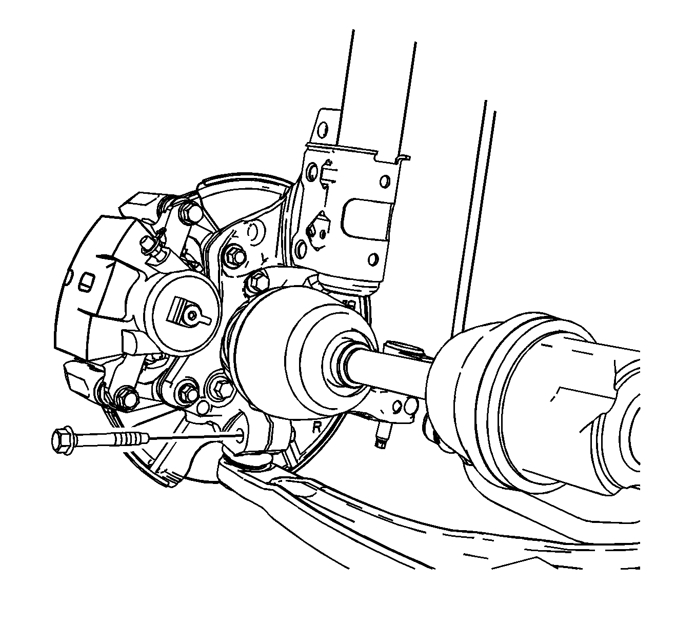
- Remove the left side ball stud from the steering knuckle. Refer to Lower Control Arm Replacement .
- Support the left frame rail with a jack stand.
- Remove the left 2 frame-to-body bolts.
- Lower the frame with jack stand and remove jack stand.
- Position the drain pan under transaxle side cover.
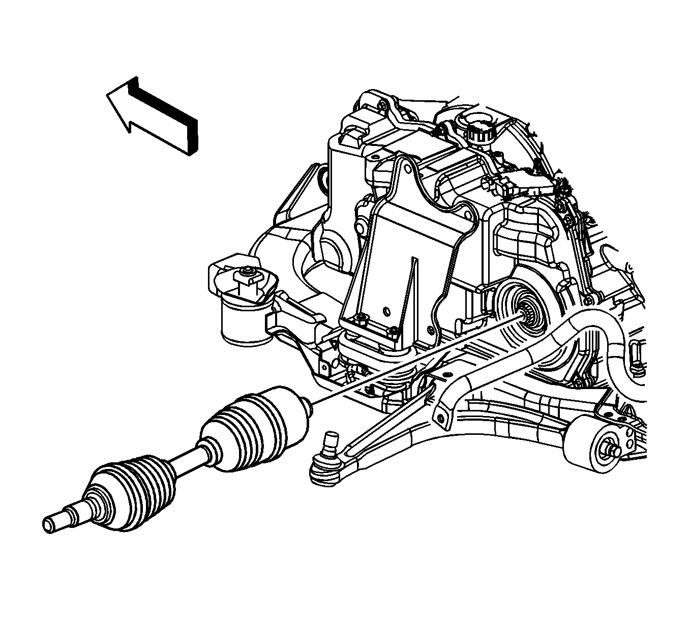
- Remove the left drive axle from the transaxle. Refer to Wheel Drive Shaft Replacement .
- Secure the drive axle to the strut assembly.
- Lower the vehicle.
- Using the engine support fixture lower the engine assembly to access the transaxle case side cover.
- Raise the vehicle.
- Remove the transaxle mount bracket. Refer to Transmission Mount Bracket Replacement - Left Side .
- Remove the remaining case side cover bolts (56, 57, 58).
- Remove the case side cover (53).
- Remove the case side cover gasket (54).
- Remove the case side cover O-ring (59).
- Clean the side cover gasket mating surfaces.

Installation Procedure
- Install the J 36850 to the case side cover O-ring (59).
- Install the O-ring (59) to the case side cover.
- Install the case side cover gasket (54).
- Install the case side cover (53).
- Install the case side cover bolts (56, 57, 58) except top bolt.
- Install the transaxle mount bracket. Refer to Transmission Mount Bracket Replacement - Left Side .
- Install the transaxle mount bracket bolts.
- Install a jack stand under the left frame rail and raise frame.
- Install and tighten the left side frame-to-body bolts.
- Install front cradle to radiator support brackets.
- Install drive axle to transaxle. Refer to Wheel Drive Shaft Replacement .
- Install the left transaxle mount. Refer to Transmission Mount Replacement - Left Side .
- Install the left side ball stud to the steering knuckle. Refer to Lower Control Arm Replacement .
- Install the steering gear-to-frame bolts. Refer to Steering Gear Replacement .
- Install the intermediate shaft to steering gear pinch bolt. Refer to Steering Gear Replacement .
- Reposition the stabilizer bar and install the stabilizer links. Refer to Stabilizer Shaft Link Replacement .
- Install the wheel speed sensor harness to four retainers on the lower control arm.
- Install the left engine splash shield. Refer to Engine Splash Shield Replacement - Left Side .
- Install the left front wheel. Refer to Tire and Wheel Removal and Installation .
- Lower the vehicle.
- Remove the engine support fixture.
- Install the top case side cover bolt (56, 58).
- Install the transaxle shift cable bracket and shift cable bracket bolts.
- Install the transaxle shift cable to the transaxle range selector.
- Connect the transaxle wiring harness connector.
- Install the battery. Refer to Battery Replacement .
- Install the air cleaner outlet duct. Refer to Air Cleaner Outlet Duct Replacement .
- Check and fill the transaxle as necessary.
- Inspect for fluid leaks.

Notice: Refer to Fastener Notice in the Preface section.

Tighten
Tighten bolts to 25 N·m (18 lb ft).
Tighten
Tighten the bolts to 95 N·m (70 lb ft).


Tighten
Tighten bolts to 25 N·m (18 lb ft).

Tighten
Tighten the bolts to 30 N·m (22 lb ft).
Notice: Refer to Transmission Overfill Notice in the Preface section.
