Power Vacuum Brake Booster Replacement ABS
Caution: Refer to Brake Fluid Irritant Caution in the Preface section.
Notice: Refer to Brake Fluid Effects on Paint and Electrical Components Notice in the Preface section.
Removal Procedure
- Turn the ignition to the OFF position.
- Raise and support the vehicle. Refer to Lifting and Jacking the Vehicle .
- Remove the left front tire and wheel assembly. Refer to Tire and Wheel Removal and Installation .
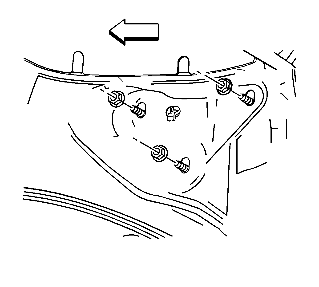
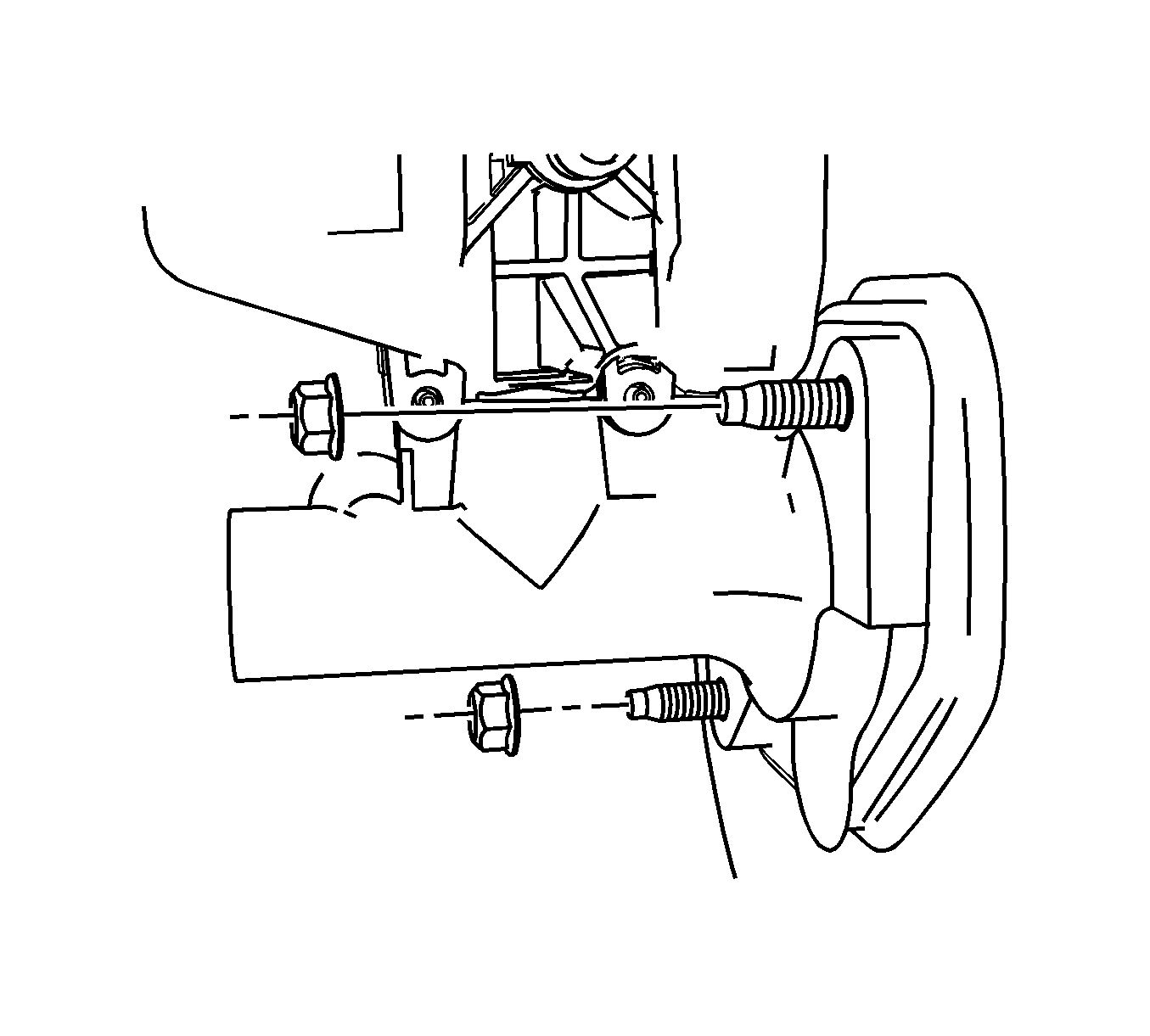
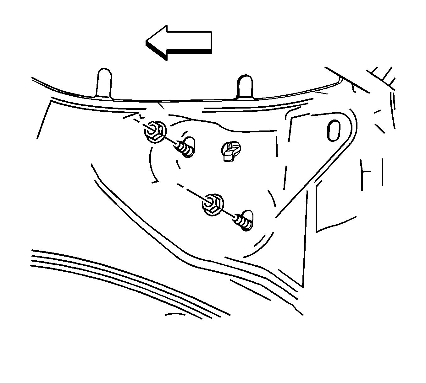
- Remove the 3 nuts that attach the electronic brake control module (EBCM)/brake pressure modulator valve (BPMV) bracket to the left front wheelhouse.
- Lower the vehicle.
- Disconnect the electrical connector from the EBCM.
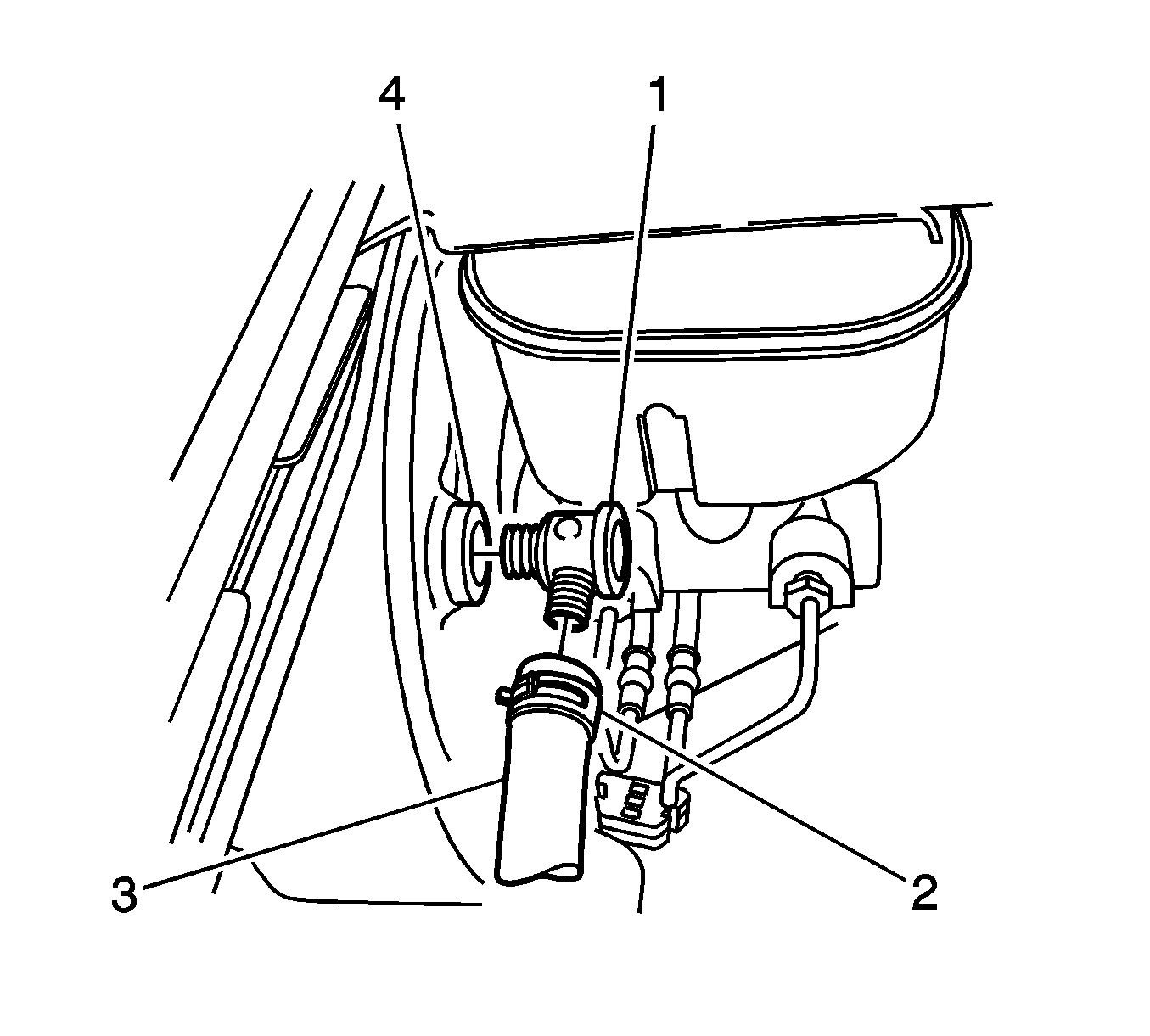
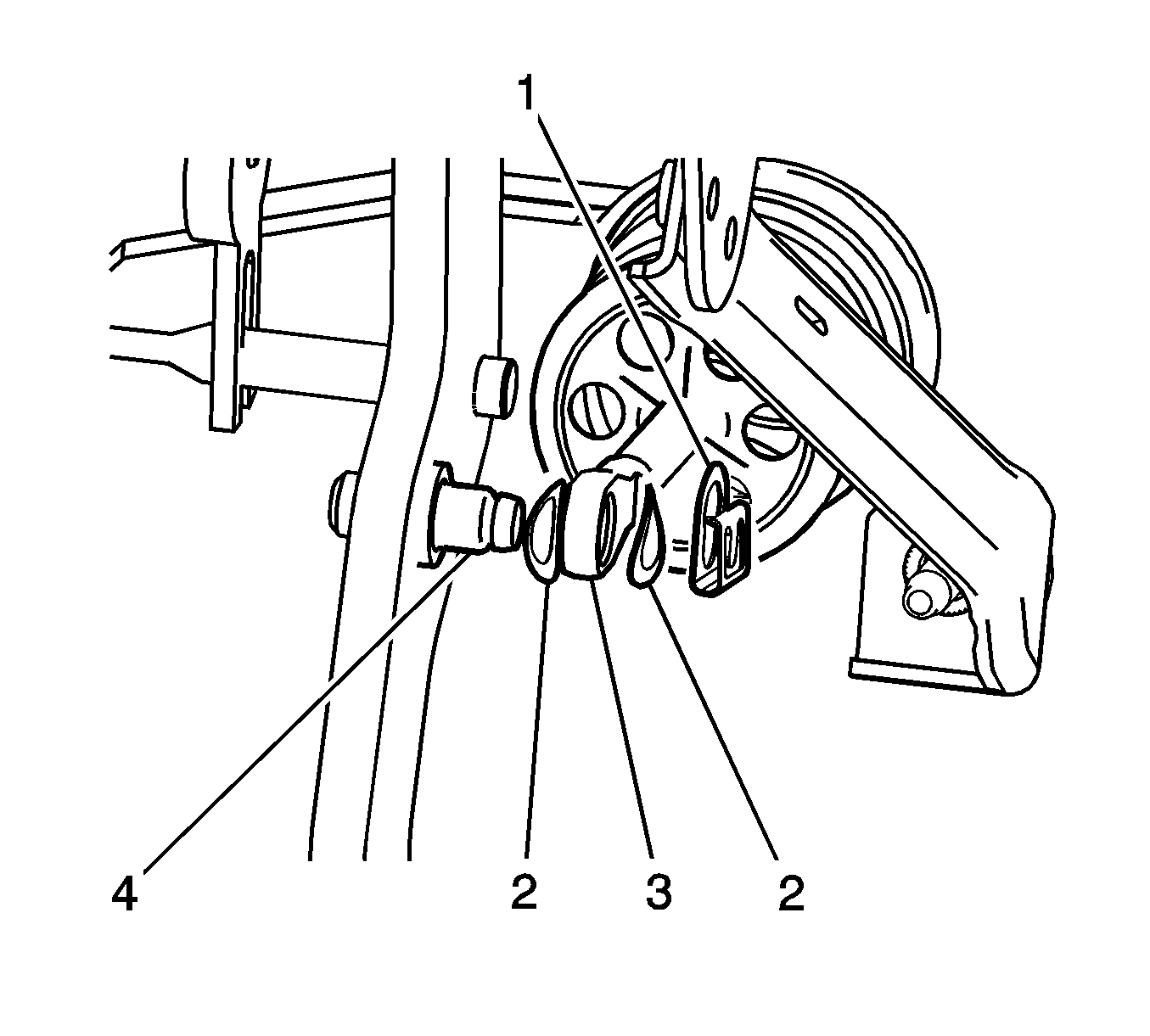
- Deplete the vacuum from the vacuum brake booster by removing the vacuum check valve (1) from the vacuum brake booster grommet (4). Do not disconnect the vacuum check valve (1) from the vacuum brake hose (3).
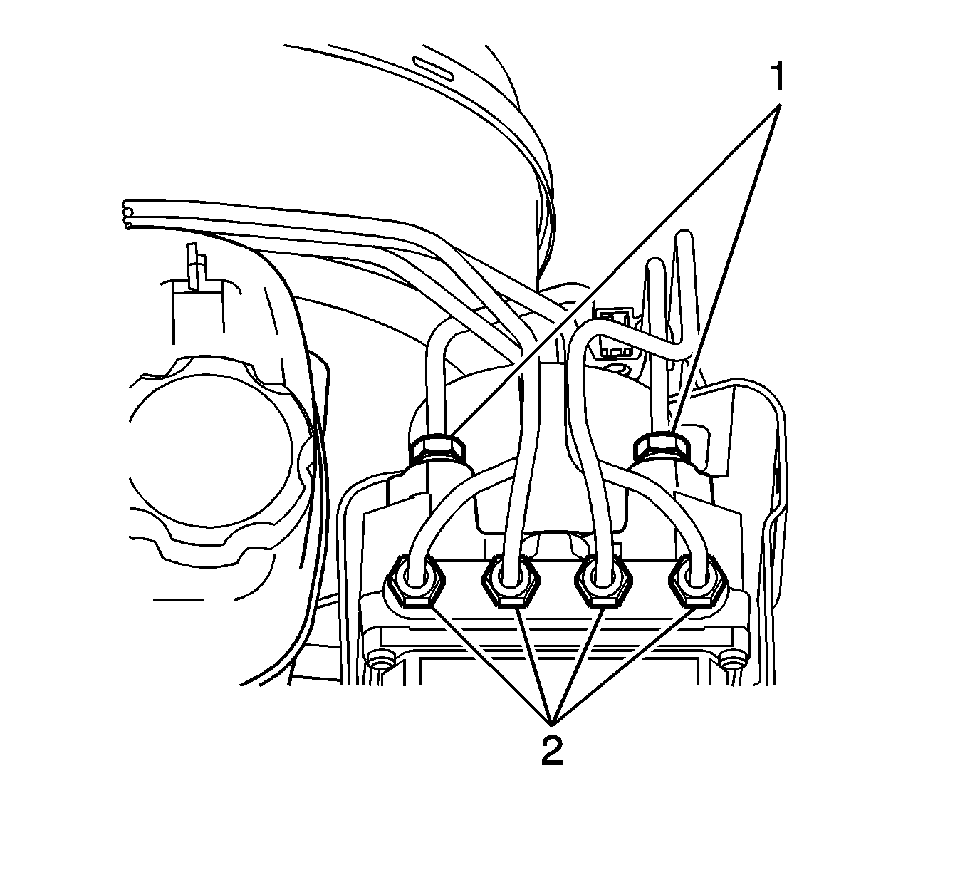
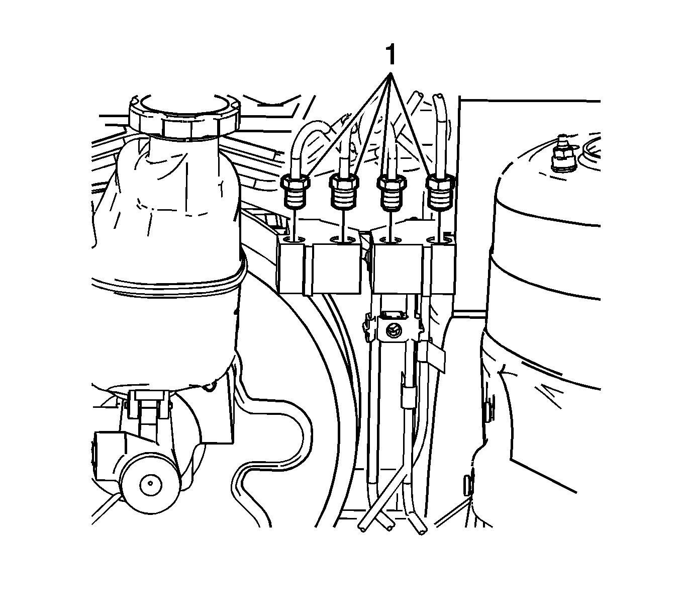
- Remove the 4 brake pipes (2) from the BPMV. Use bleeder valve caps or similar rubber caps to plug the brake pipes in order to prevent brake fluid loss and contamination.
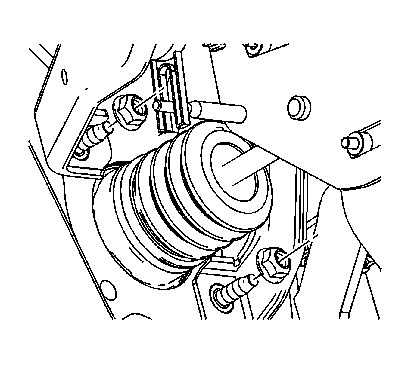
- Remove the master cylinder nuts from the vacuum brake booster.
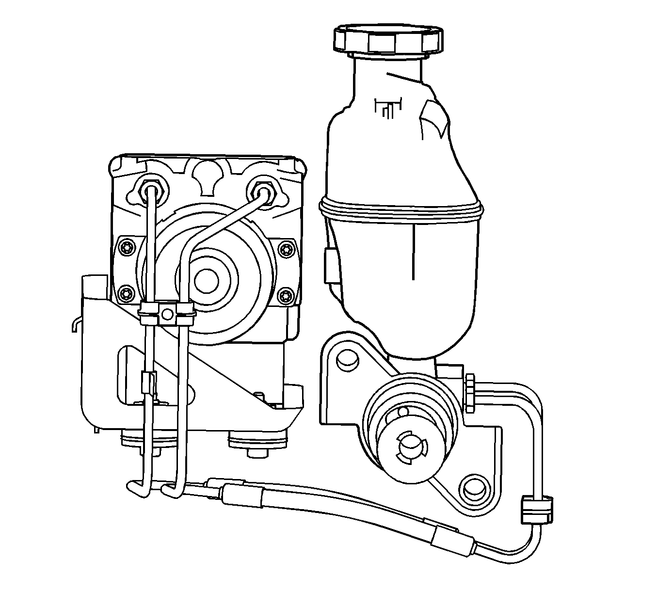
- Remove the EBCM/BPMV bracket assembly with the brake master cylinder.
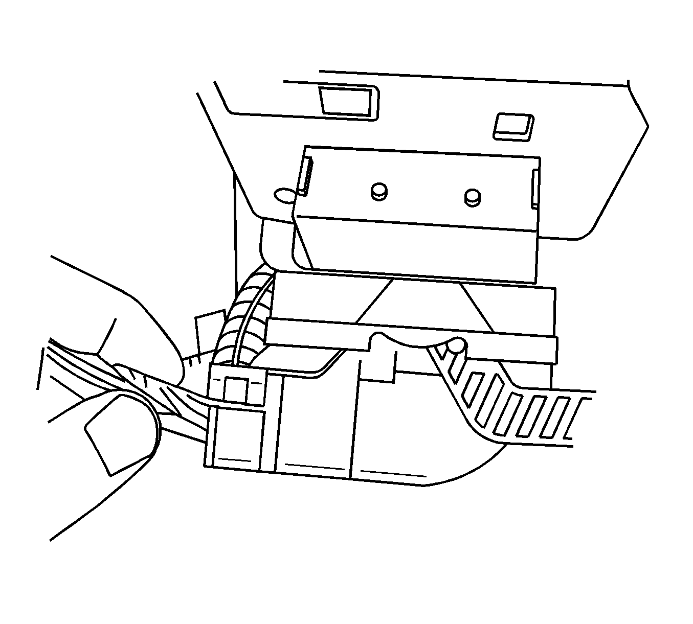
- Remove the closeout panel. Refer to Instrument Panel Insulator Panel Replacement - Left Side .
- Remove the electrical connector from the brake apply sensor.
- Remove the 2 brake pedal assembly to cowl mounting nuts.
- Disconnect the brake pedal pushrod retaining clip (1) the wave washers (2) and the brake booster pushrod (3) from the brake pedal pin (4).
- Remove the booster from the vehicle.
Notice: Always connect or disconnect the wiring harness connector from the EBCM/EBTCM with the ignition switch in the OFF position. Failure to observe this precaution could result in damage to the EBCM/EBTCM.
Tilt the vacuum brake booster slightly in order to work the booster pushrod off the brake pedal pin. Do not apply excessive side pressure on the pushrod.
Installation Procedure
- Install the booster to the vehicle.
- Tilt the vacuum brake booster slightly in order to work the booster pushrod onto the brake pedal pin. Do not apply excessive side pressure on the pushrod. Align the pushrod with the pedal and assemble.
- Connect the brake pedal pushrod retaining clip (1) the wave washers (2) and the brake booster pushrod (3) to the brake pedal pin (4).
- Install the 2 brake pedal assembly to cowl mounting nuts.
- Install the electrical connector to the brake apply sensor.
- Install the closeout panel. Refer to Instrument Panel Insulator Panel Replacement - Left Side .
- Install the EBCM/BPMV bracket assembly and the master cylinder to the vehicle.
- Install the master cylinder nuts to the vacuum brake booster.
- Raise the vehicle.
- Install the 3 nuts that attach the EBCM/BPMV bracket assembly to the left wheelhouse.
- Install the left front tire and wheel assembly. Refer to Tire and Wheel Removal and Installation .
- Lower the vehicle.
- Remove the caps or plugs from the 4 brake pipes (2) and install the 4 brake pipes (2) to the BPMV.
- Connect the electrical connector to the EBCM.
- Connect the vacuum brake booster check valve (1) to the vacuum brake booster grommet (4).
- Bleed the hydraulic brake system. Refer to Hydraulic Brake System Bleeding .
- Calibrate the brake pedal position sensor. Refer to Brake Pedal Position Sensor Calibration .
Notice: Refer to Fastener Notice in the Preface section.
Tighten
Tighten the nuts to 15 N·m (11 lb ft).
Important: Ensure the gasket on the outside barrel of the master cylinder is positioned properly and is free of cuts and tears.
Tighten
Tighten the nuts to 25 N·m (18 lb ft).
Tighten
Tighten the nuts to 10 N·m (89 lb in).
Tighten
Tighten the pipes to 20 N·m (15 lb ft).
Power Vacuum Brake Booster Replacement W/O ABS
Caution: Refer to Brake Fluid Irritant Caution in the Preface section.
Notice: Refer to Brake Fluid Effects on Paint and Electrical Components Notice in the Preface section.
Removal Procedure
- Turn the ignition to the OFF position.
- Raise and support the vehicle. Refer to Lifting and Jacking the Vehicle .
- Remove the left front tire and wheel assembly. Refer to Tire and Wheel Removal and Installation .
- Remove the 2 nuts that attach the proportioning valve bracket to the left front wheelhouse.
- Lower the vehicle.
- Deplete the vacuum from the vacuum brake booster by removing the vacuum check valve (1) from the vacuum brake booster grommet (4). Do not disconnect the vacuum check valve (1) from the vacuum brake hose (3).
- Remove the 4 brake pipes (1) from the proportioning valve. Use bleeder valve caps or similar rubber caps to plug the brake pipes in order to prevent brake fluid loss and contamination.
- Remove the master cylinder nuts from the vacuum brake booster.
- Remove the proportioning valve bracket assembly with the brake master cylinder from the vehicle.
- Remove the closeout panel. Refer to Instrument Panel Insulator Panel Replacement - Left Side .
- Remove the electrical connector from the brake apply sensor.
- Remove the 2 brake pedal assembly to cowl mounting nuts.
- Disconnect the brake pedal pushrod retaining clip (1) the wave washers (2) and the brake booster pushrod (3) from the brake pedal pin (4).
- Remove the booster from the vehicle.
Tilt the vacuum brake booster slightly in order to work the booster pushrod off the brake pedal pin. Do not apply excessive side pressure on the pushrod.
Installation Procedure
- Install the booster to the vehicle.
- Tilt the vacuum brake booster slightly in order to work the booster pushrod onto the brake pedal pin. Do not apply excessive side pressure on the pushrod. Align the pushrod with the pedal and assemble.
- Connect the brake pedal pushrod retaining clip (1) the wave washers (2) and the brake booster pushrod (3) to the brake pedal pin (4).
- Install the 2 brake pedal assembly to cowl mounting nuts.
- Install the electrical connector to the brake apply sensor.
- Install the closeout panel. Refer to Instrument Panel Insulator Panel Replacement - Left Side .
- Install the proportioning valve bracket assembly with the brake master cylinder to the vehicle.
- Install the master cylinder nuts to the vacuum brake booster.
- Raise the vehicle.
- Install the 2 nuts that attach the proportioning valve bracket assembly to the left wheelhouse.
- Install the left front tire and wheel assembly. Refer to Tire and Wheel Removal and Installation .
- Lower the vehicle.
- Remove the caps or plugs from the 4 brake pipes (1) and install the 4 brake pipes (1) to the proportioning valve.
- Connect the vacuum brake booster check valve (1) to the vacuum brake booster grommet (4).
- Bleed the hydraulic brake system. Refer to Hydraulic Brake System Bleeding .
- Calibrate the brake pedal position sensor. Refer to Brake Pedal Position Sensor Calibration .
Notice: Refer to Fastener Notice in the Preface section.
Tighten
Tighten the nuts to 15 N·m (11 lb ft).
Important: Ensure the gasket on the outside barrel of the master cylinder is positioned properly and is free of cuts and tears.
Tighten
Tighten the nuts to 25 N·m (18 lb ft).
Tighten
Tighten the nuts to 10 N·m (86 lb in).
Tighten
Tighten the pipes to 20 N·m (15 lb ft).
