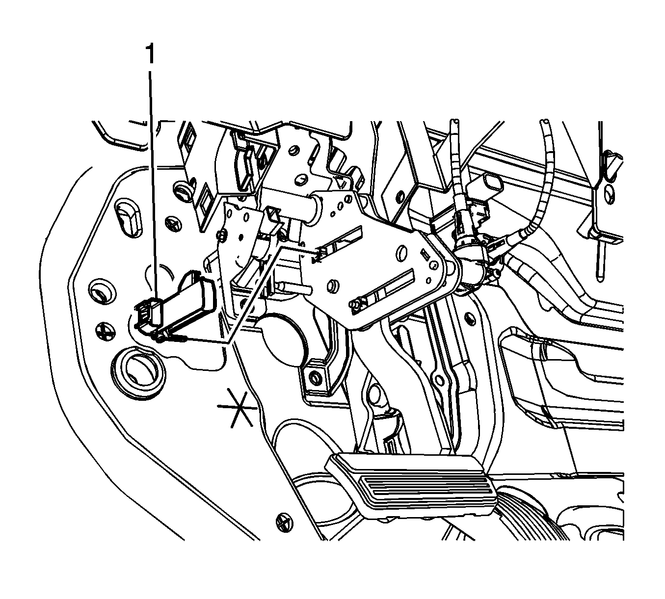
For 1990-2009 cars only
Removal Procedure
- Remove the closeout panel. Refer to Instrument Panel Insulator Panel Replacement - Left Side.
- Remove the steering wheel stub shaft bolt and position the steering wheel stub shaft away from the steering column in order to gain access to the brake pedal adjustment position sensor. Refer to Intermediate Steering Shaft Replacement.
- Remove the electrical connector from the brake and accelerator pedal adjustment position sensor.
- Remove the brake and accelerator pedal adjustment position sensor (1).

Installation Procedure
- Install the brake and accelerator pedal adjustment position sensor (1) to the brake pedal bracket. Ensure the brake pedal position sensor tab locks into the brake pedal bracket and the sensors arm is correctly installed.
- Install the electrical connector to the brake and accelerator pedal adjustment position sensor.
- Install the steering wheel stub shaft to the steering column. Refer to Intermediate Steering Shaft Replacement.
- Install the closeout panel. Refer to Instrument Panel Insulator Panel Replacement - Left Side.

Important: Ensure that the brake and accelerator pedal adjustment position sensor is installed correctly to the bracket. The brake and accelerator pedal adjustment position sensor has a sensing arm that must be installed over the brake pedal actuation arm to insure it is sensing brake pedal position.
