For 1990-2009 cars only
Removal Procedure
- Raise and support the vehicle. Refer to Lifting and Jacking the Vehicle .
- Remove the front wheel. Refer to Tire and Wheel Removal and Installation .
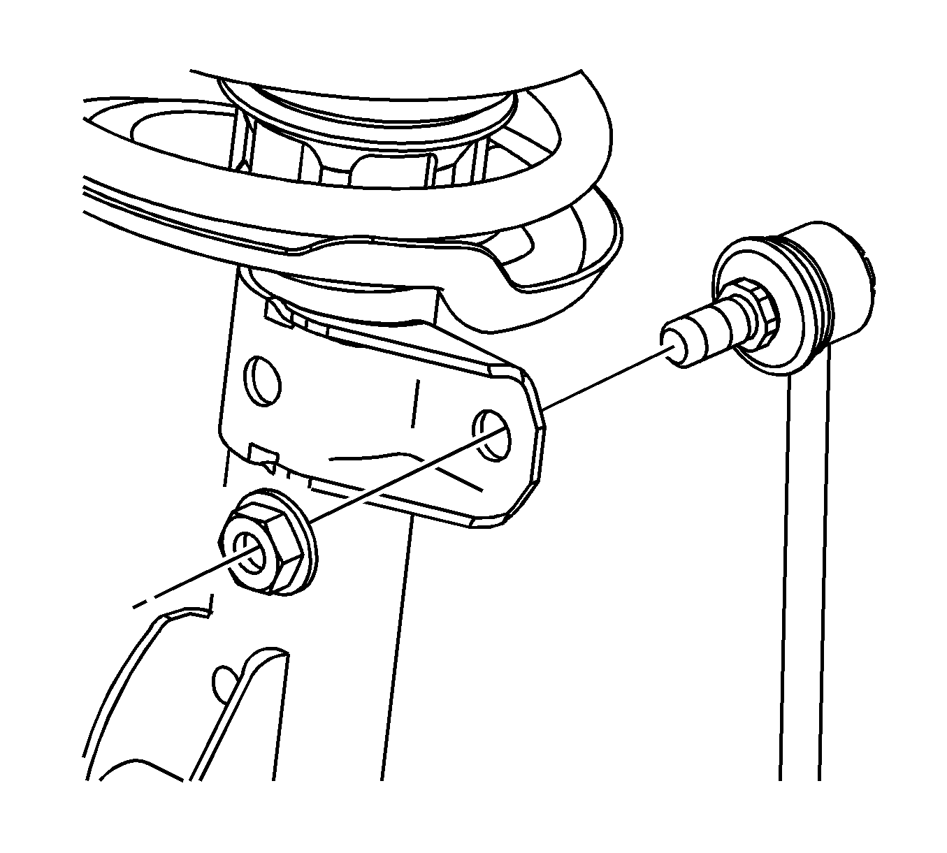
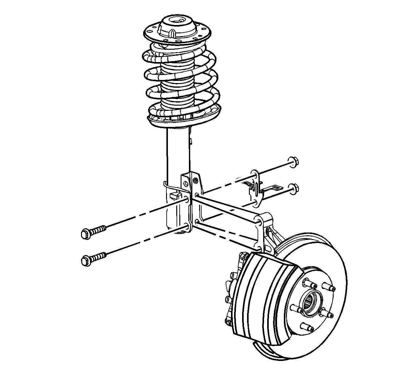
- Disconnect the stabilizer link from the strut.
- Remove the strut to steering knuckle nuts.
- If applicable, reposition the wheel speed sensor/ABS harness and bracket.
- Remove the strut to steering knuckle bolts.
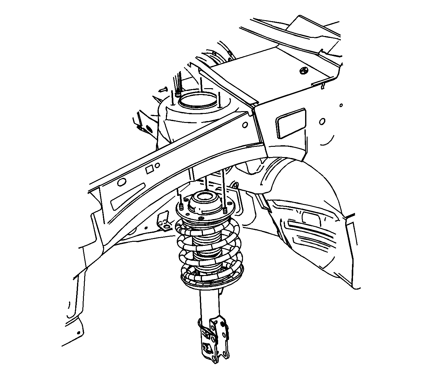
- Remove the upper strut cap to body nuts.
- Remove the strut from the vehicle.
- For strut replacement, refer to Strut, Strut Component, and Spring Replacement .
Important: In order to prevent damage to the CV joint boot, place a shop towel over the CV joint.
Installation Procedure
- Position the strut to the vehicles strut tower, using the alignment pin as a guide.
- Install the upper strut cap to body nuts.
- Install the strut to steering knuckle bolts leaving the nuts off.
- If applicable, place the wheel speed sensor harness and bracket to the bolt end.
- Install the strut to steering knuckle nuts.
- Connect the stabilizer link to the strut.
- Install the front wheel. Refer to Tire and Wheel Removal and Installation .
- Lower the vehicle.
- Road test the vehicle and test for leads and pulls. If vehicle leads or pulls refer to Wheel Alignment Measurement .
Important: It may be necessary to rotate the upper strut mount cover guide to match the hole in the strut tower.
Notice: Refer to Fastener Notice in the Preface section.
Tighten
Tighten the nut to 25 N·m (18 lb ft).
Tighten
Tighten the nuts to 120 N·m (89 lb ft).
Tighten
Tighten the link to 65 N·m (48 lb ft).
