GM Service Manual Online
For 1990-2009 cars only
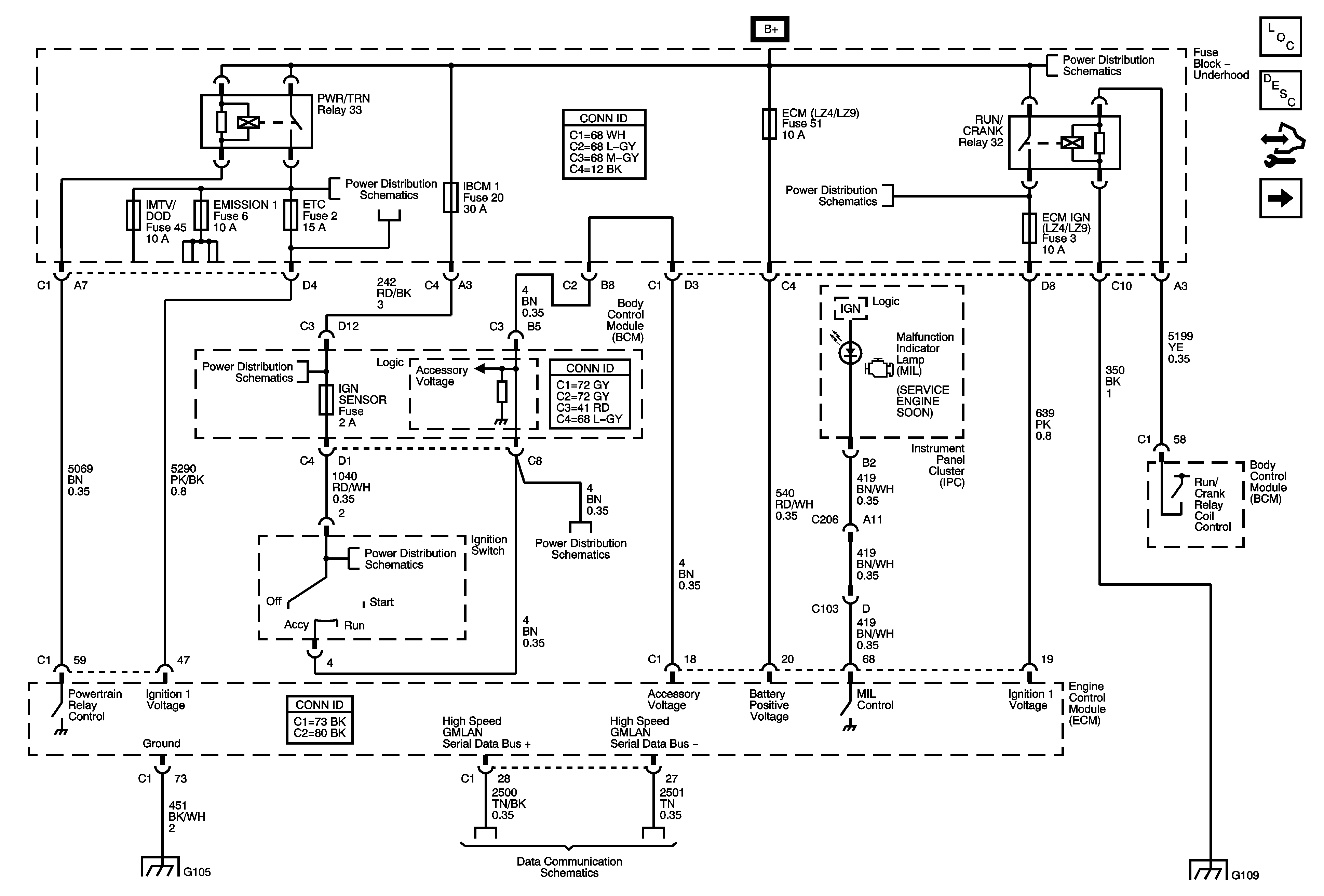
Figure 1:

DLC, Ground, MIL and Power


Object Number: 1782777  Size: FS
Master Electrical Component List
Engine Control Module Description
Control Module References
5-Volt and Low References
Underhood Fuse Block B+
Underhood Fuse Block RUN/CRANK Relay, ABS, IGN 1, INJ, PCM IGN 1 and TRANS Fuses
Underhood Fuse Block B+
Underhood Fuse Block IBCM 1 Fuse, BCM AIRBAG (BATT), CLUSTER/THEFT, HVAC CTRL (BATT), IGN SENSOR and RADIO Fuses and Ignition Switch
G103, G104, and G105
Power, Ground, High Speed GMLAN Serial Data
G109
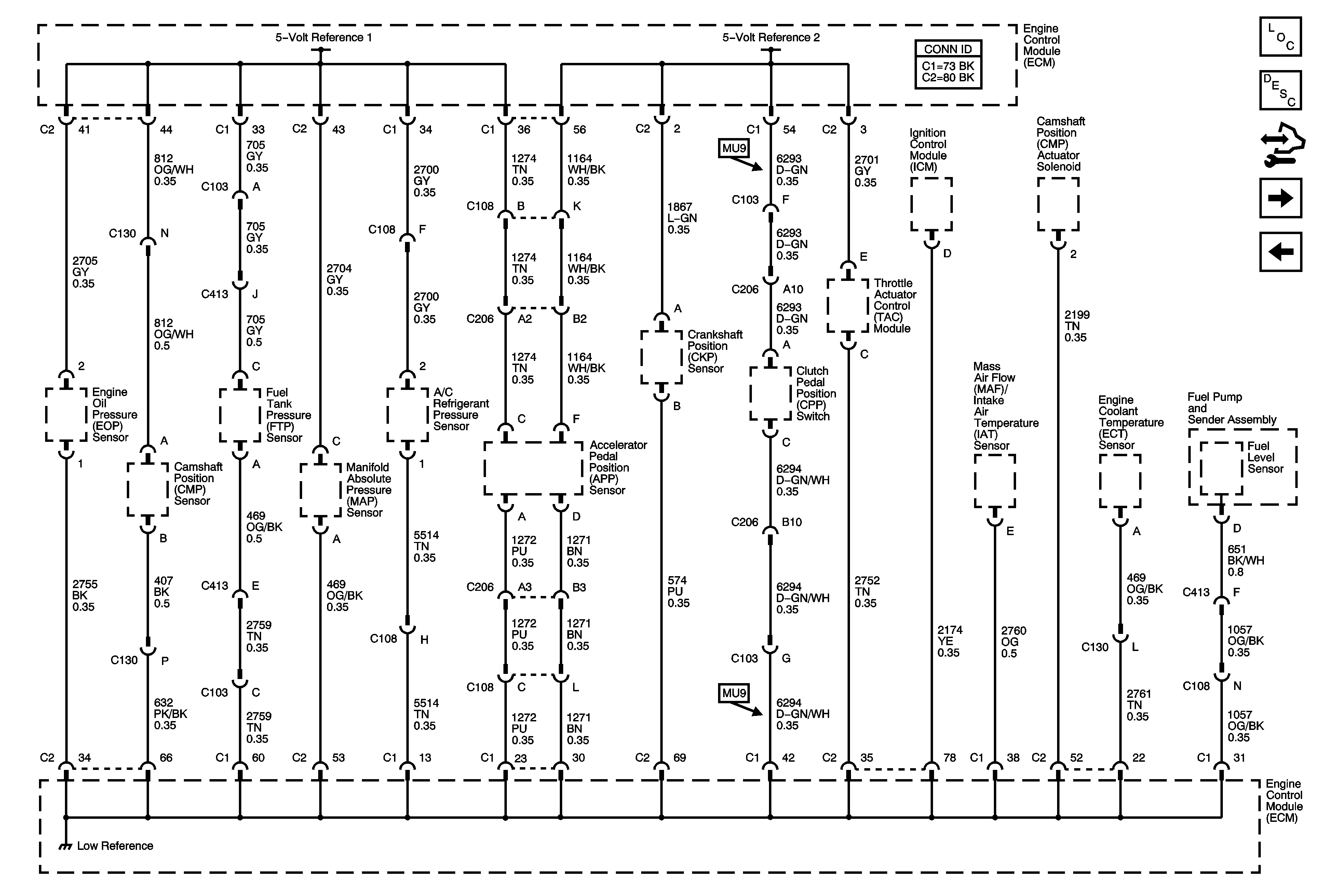
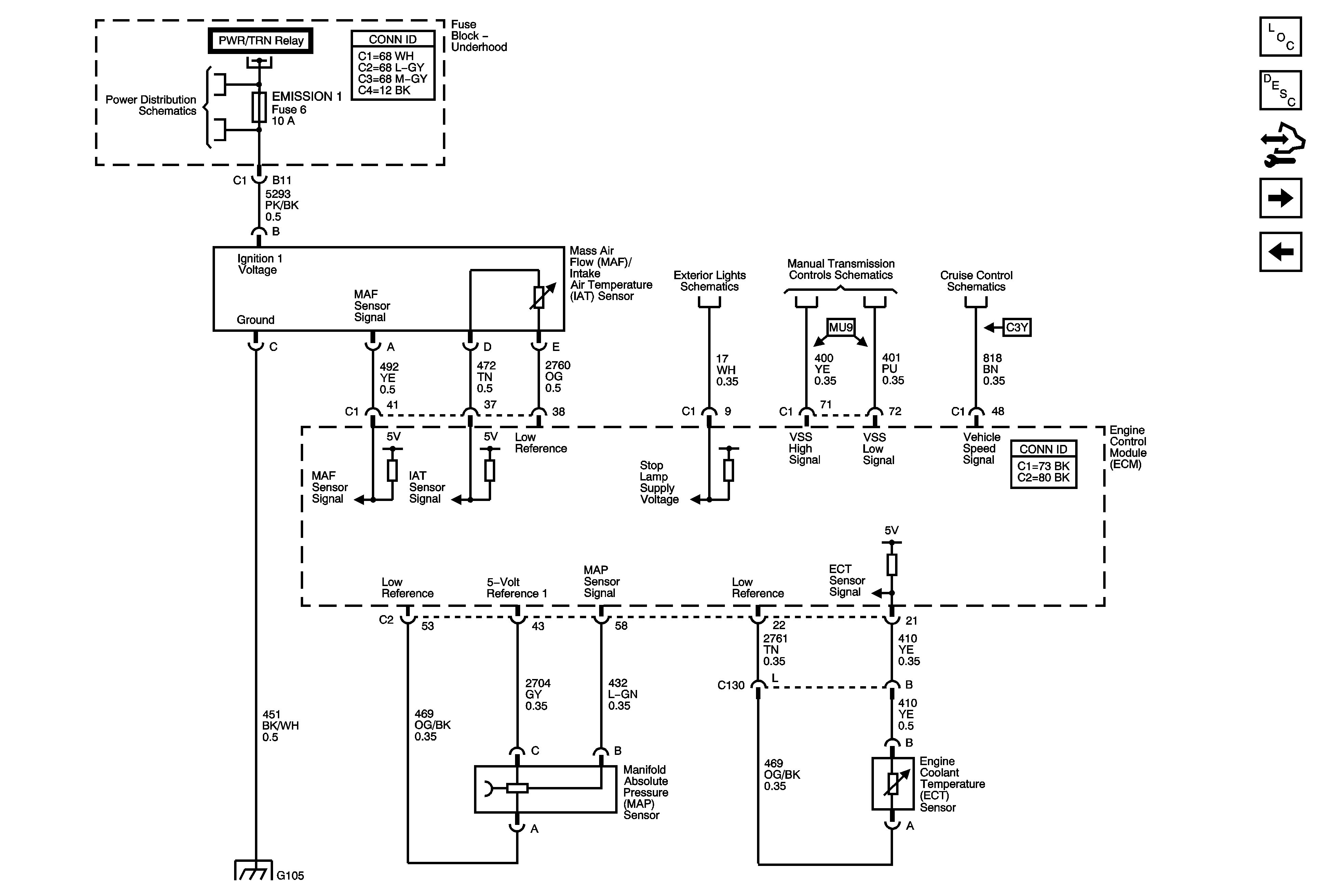
Figure 2:

5-Volt and Low References


Object Number: 1782778  Size: FS
Master Electrical Component List
Engine Control Module Description
Control Module References
MAF, VSS and Extended Brake Travel Switch
DLC, Ground, MIL and Power
Figure 3:

MAF, VSS and Extended Brake Travel Switch


Object Number: 1782779  Size: FS
Master Electrical Component List
Engine Control Module Description
Control Module References
Heated Oxygen Sensors
5-Volt and Low References
Underhood Fuse Block A/C CLUTCH and PWR/TRN Relays, EMISSION 1, ETC, IGN MOD and IMTV/DOD Fuses
Turn Signals and Stop Lamps
Manual Transmission Schematics
Brake Pedal Position Sensor and Stop Lamp Switch Signal
G103, G104, and G105
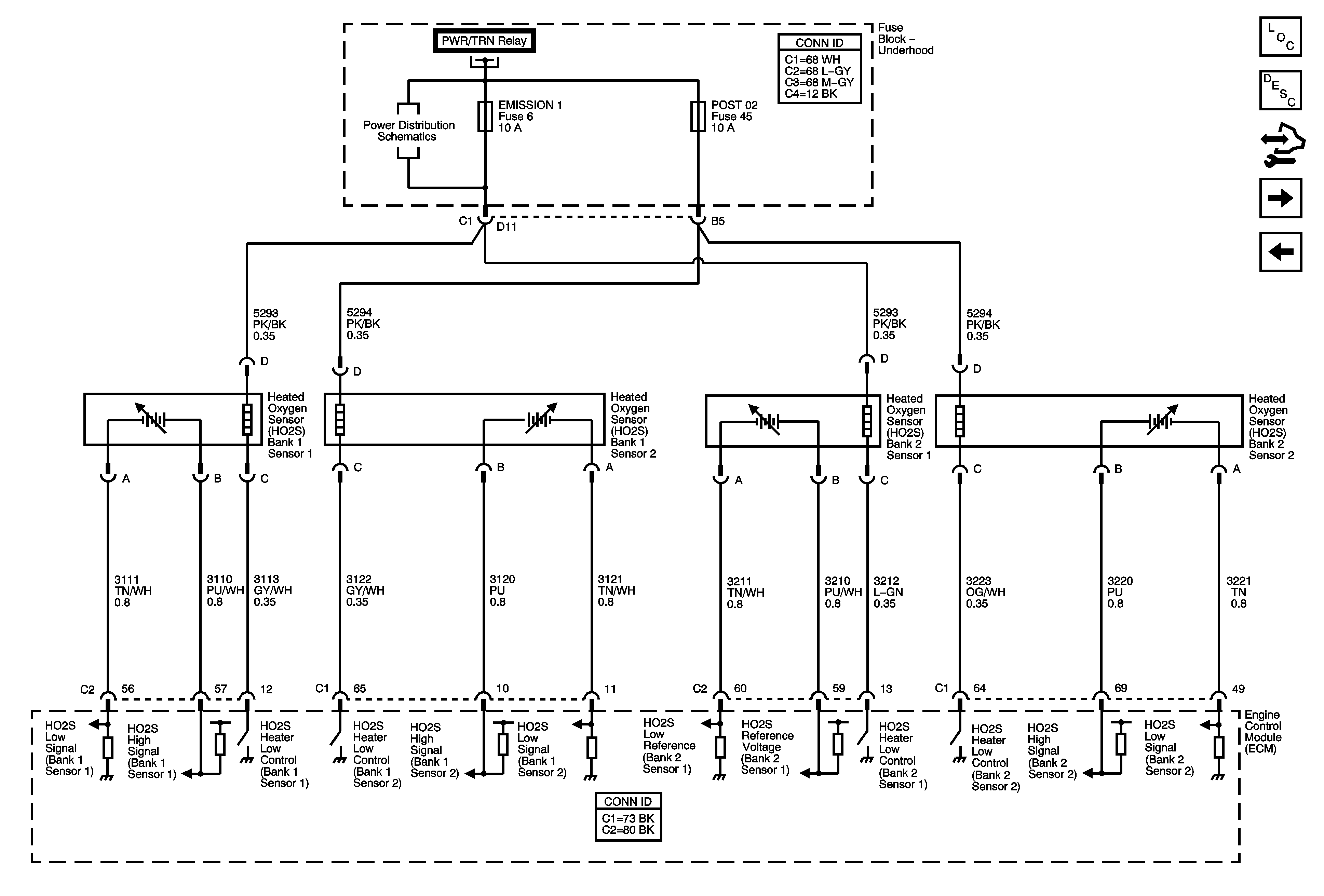
Figure 4:

Heated Oxygen Sensors


Object Number: 1782780  Size: FS
Master Electrical Component List
Engine Control Module Description
Control Module References
Electronic Throttle Controls
MAF, VSS and Extended Brake Travel Switch
Underhood Fuse Block A/C CLUTCH and PWR/TRN Relays, EMISSION 1, ETC, IGN MOD and IMTV/DOD Fuses
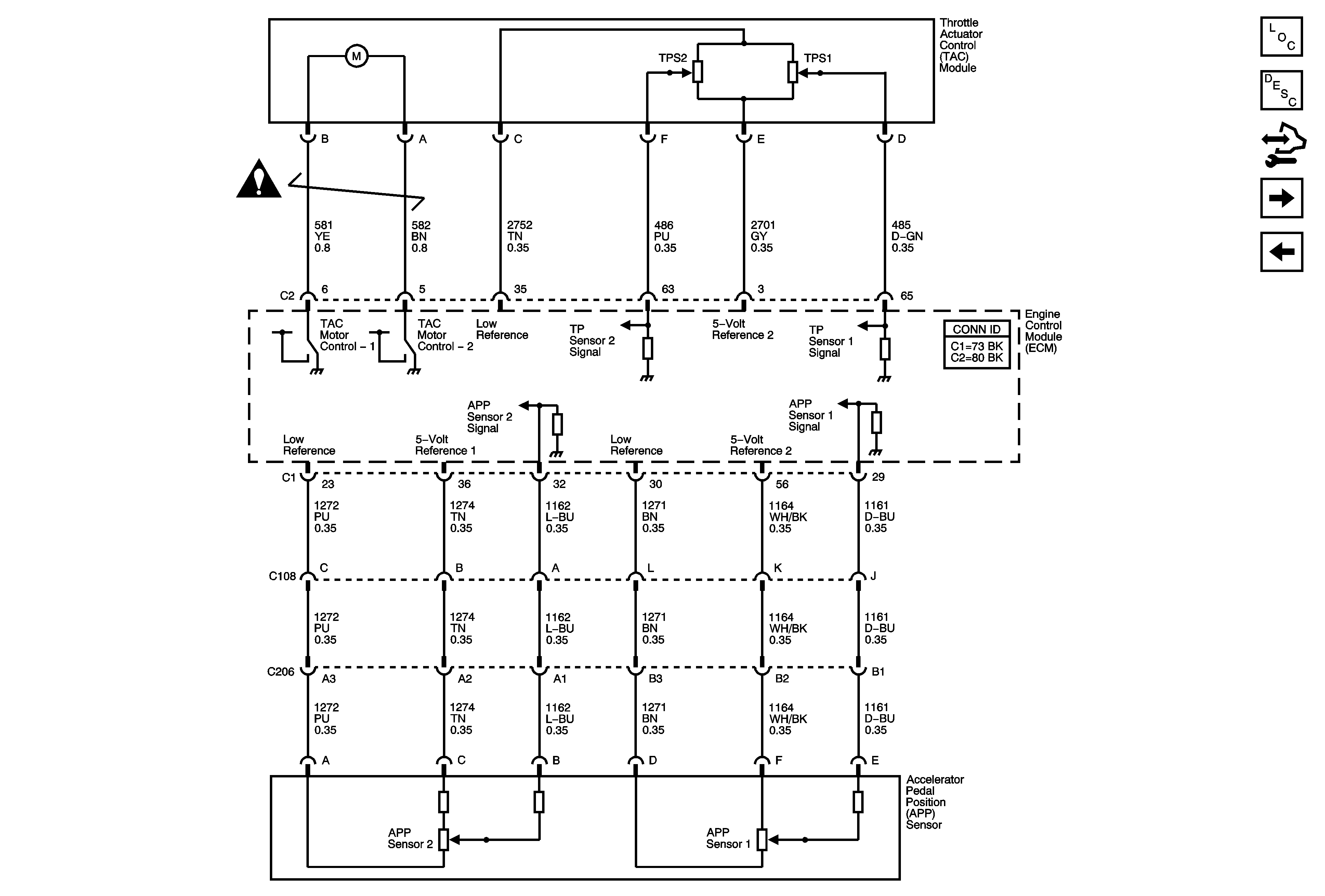
Figure 5:

Electronic Throttle Controls


Object Number: 1782781  Size: FS
Master Electrical Component List
Throttle Actuator Control (TAC) System Description
Control Module References
Ignition System
Heated Oxygen Sensors
Engine Controls Schematic Icons
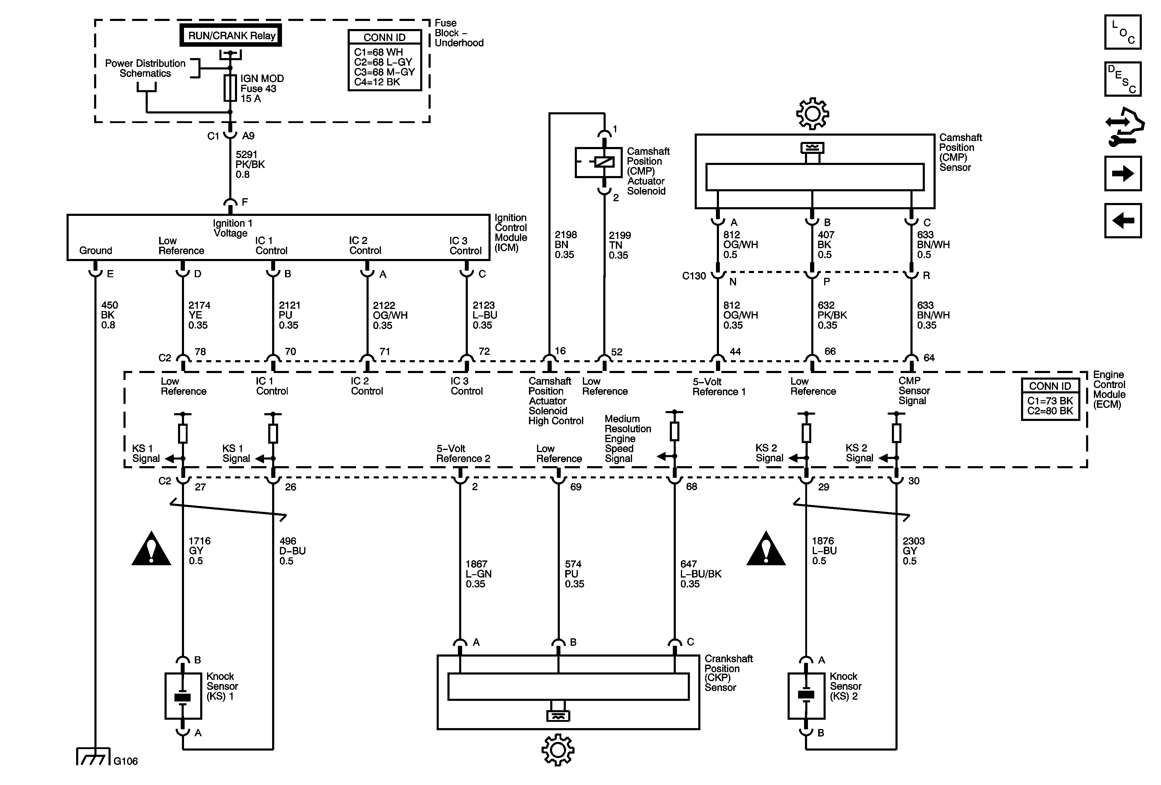
Figure 6:

Ignition System


Object Number: 1782783  Size: FS
Master Electrical Component List
Electronic Ignition (EI) System Description
Control Module References
Fuel Injectors and Fuel Pump
Electronic Throttle Controls
Underhood Fuse Block A/C CLUTCH and PWR/TRN Relays, EMISSION 1, ETC, IGN MOD and IMTV/DOD Fuses
Engine Controls Schematic Icons
G106
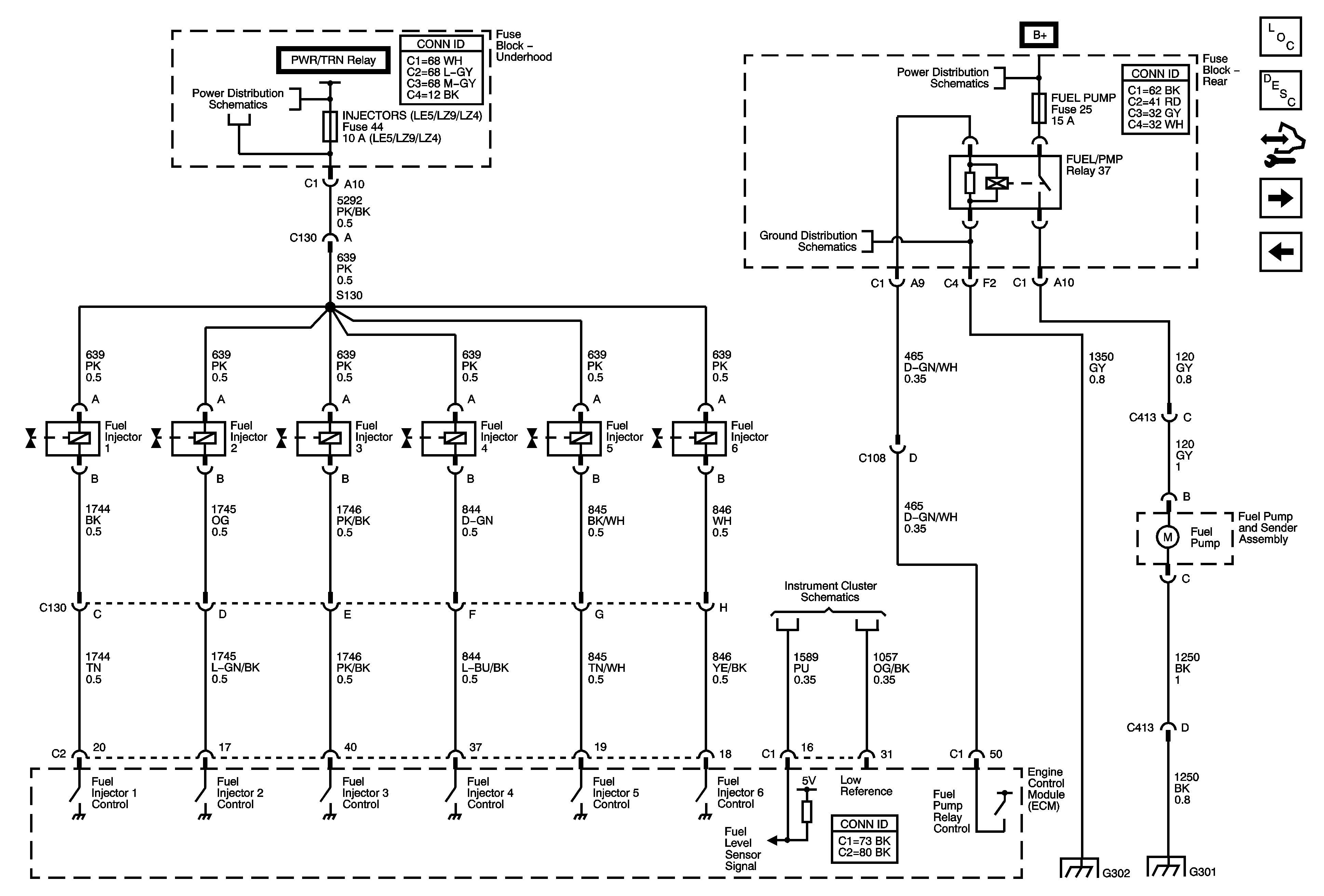
Figure 7:

Fuel Injectors and Fuel Pump


Object Number: 1782785  Size: FS
Master Electrical Component List
Fuel System Description
Control Module References
EVAP Controls, FTP Sensor, IMT Valve
Ignition System
Underhood Fuse Block A/C CLUTCH and PWR/TRN Relays, EMISSION 1, ETC, IGN MOD and IMTV/DOD Fuses
Underhood Fuse Block RBEC 2 Fuse and RUN RLY, BCM HVAC BLOWER HIGH and RUN Relays, HVAC BLOWER and HVAC CTRL (IGN) Fuses, Rear Fuse Block FUEL, PARK LPS and TRUNK Relays, DRV ST, EMISSION 2, FOLDING T
G302
Indicators
G302
G301
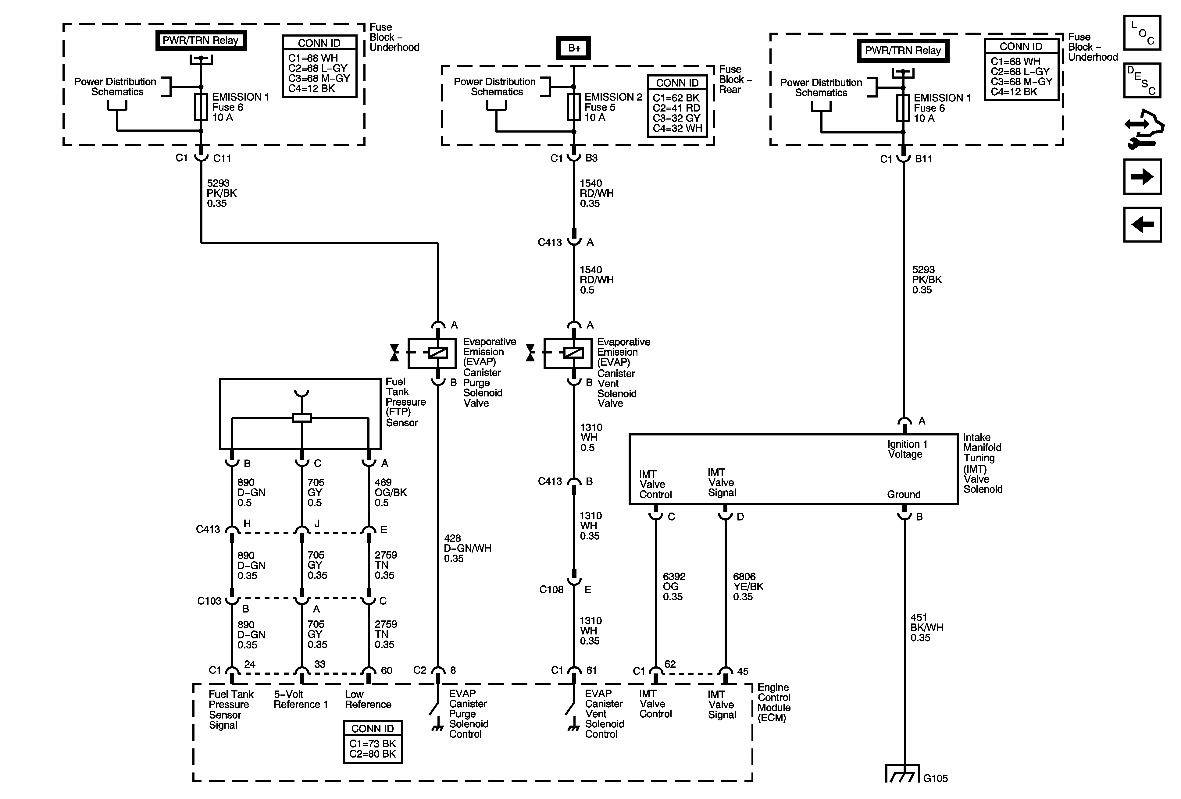
Figure 8:

EVAP Controls, FTP Sensor, IMT Valve


Object Number: 1782786  Size: FS
Master Electrical Component List
Evaporative Emission Control System Description
Control Module References
Controlled/Monitored Subsystem References
Fuel Injectors and Fuel Pump
Underhood Fuse Block A/C CLUTCH and PWR/TRN Relays, EMISSION 1, ETC, IGN MOD and IMTV/DOD Fuses
Underhood Fuse Block RBEC 2 Fuse and RUN RLY, BCM HVAC BLOWER HIGH and RUN Relays, HVAC BLOWER and HVAC CTRL (IGN) Fuses, Rear Fuse Block FUEL, PARK LPS and TRUNK Relays, DRV ST, EMISSION 2, FOLDING T
Underhood Fuse Block A/C CLUTCH and PWR/TRN Relays, EMISSION 1, ETC, IGN MOD and IMTV/DOD Fuses
G103, G104, and G105
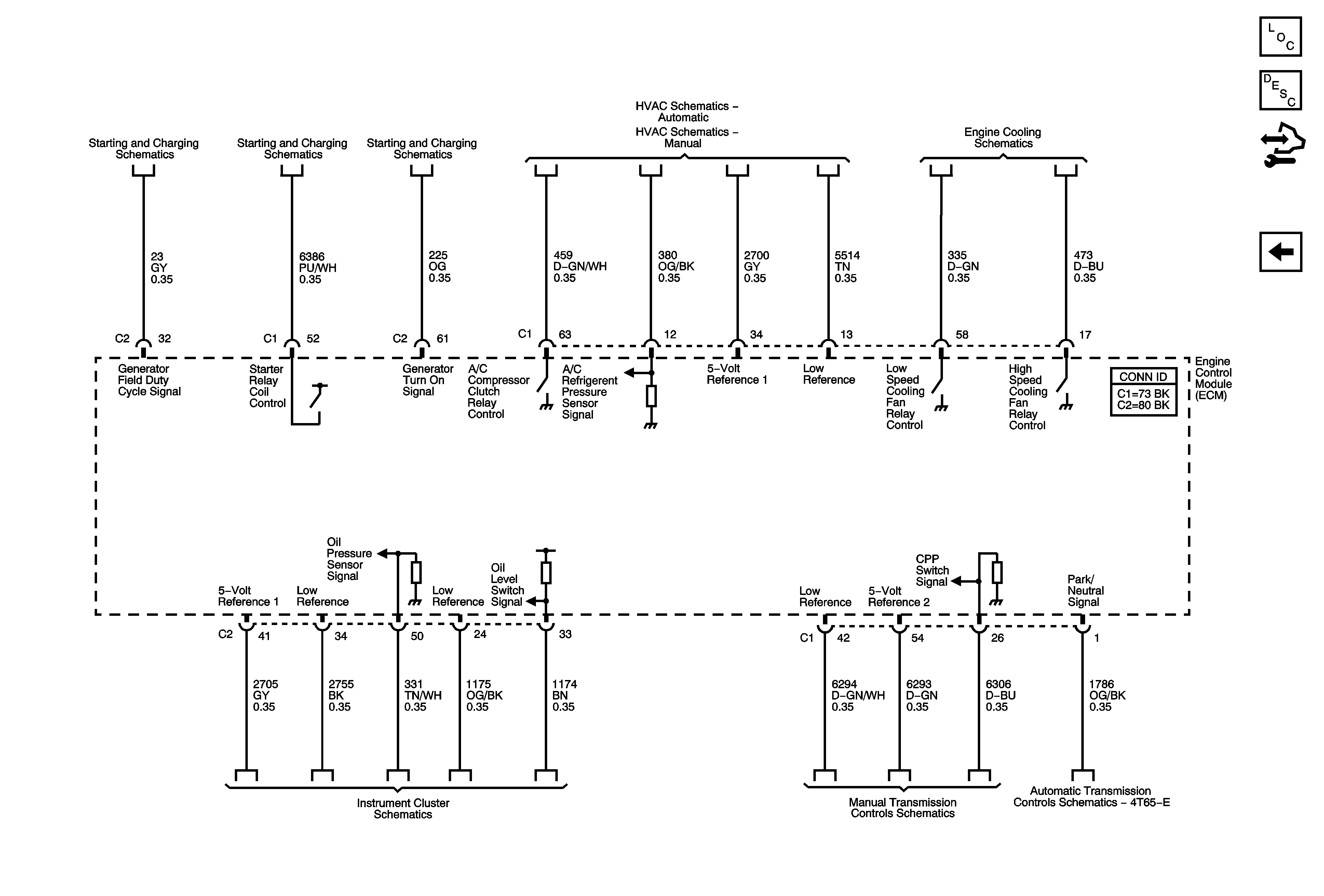
Figure 9:

Controlled/Monitored Subsystem References


Object Number: 1782787  Size: FS
Master Electrical Component List
Engine Control Module Description
Control Module References
EVAP Controls, FTP Sensor, IMT Valve
Charging System
Starting System - LZ4/LZ9
Charging System
Ambient Air Temperature Sensor and Compressor Controls
Cooling Fans
Indicators
Manual Transmission Schematics
Internal Mode Switch (IMS)