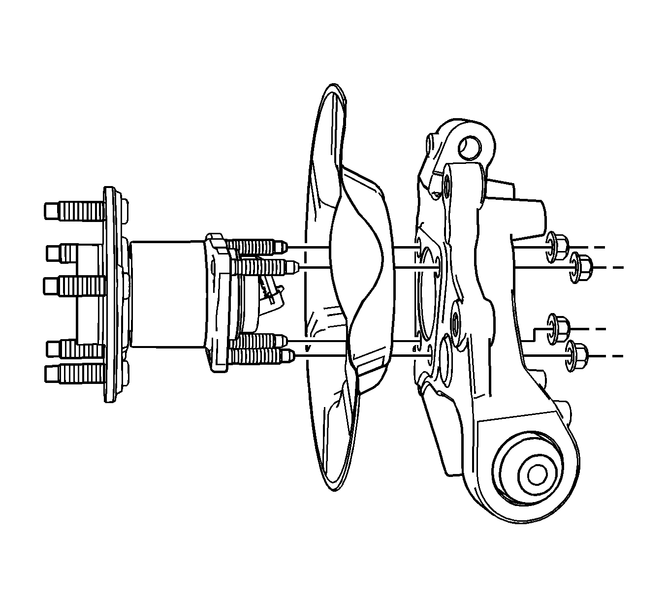
For 1990-2009 cars only
Removal Procedure
- Raise and support the vehicle. Refer to Lifting and Jacking the Vehicle .
- Remove the tire and wheel assembly. Refer to Tire and Wheel Removal and Installation .
- Remove the brake rotor. Refer to Rear Brake Rotor Replacement .
- Disconnect the electrical connector from the wheel speed sensor, if equipped with ABS.
- Remove the stabilizer link bolt at the knuckle and position the stabilizer link out of the way in order to provide access to the wheel bearing/hub nuts. Refer to Stabilizer Shaft Replacement .
- Remove the 4 wheel bearing/hub assembly nuts.
- Remove the wheel bearing/hub assembly from the knuckle.

Installation Procedure
- Install the wheel bearing/hub assembly to the knuckle.
- Install the 4 wheel bearing/hub assembly nuts.
- Connect the stabilizer link bolt at the knuckle. Refer to Stabilizer Shaft Replacement .
- Connect the electrical connector to the wheel speed sensor, if equipped with ABS.
- Install the brake rotor. Refer to Rear Brake Rotor Replacement .
- Install the tire and wheel assembly. Refer to Tire and Wheel Removal and Installation .
- Lower the vehicle.

Notice: Refer to Fastener Notice in the Preface section.
Tighten
Tighten the nuts to 63 N·m (47 lb ft).
