Removal Procedure
- Relieve the fuel system pressure. Refer to Fuel Pressure Relief .
- Disconnect the negative battery cable.
- Remove the engine cover bolts and cover.
- Disconnect the electronic throttle control connector.
- Disconnect the intake air temperature sensor.
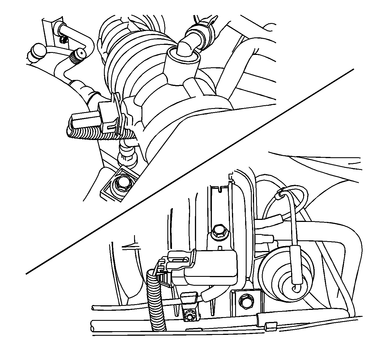
- Disconnect the camshaft position sensor.
- Disconnect the manifold absolute pressure sensor.
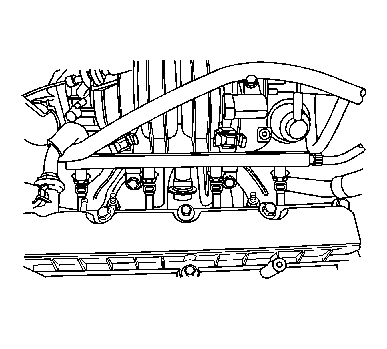
- Disconnect the fuel injector harness connectors.
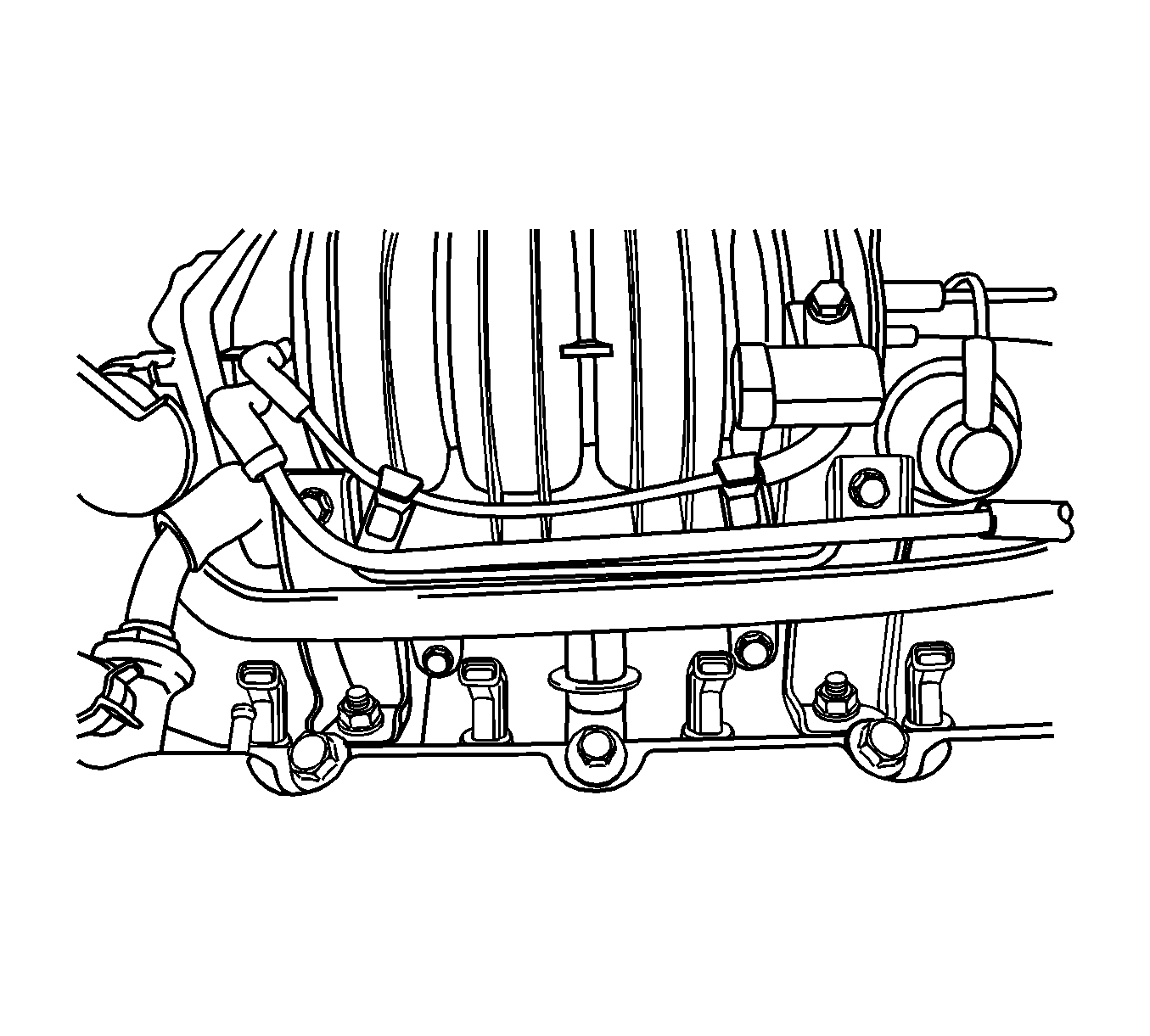
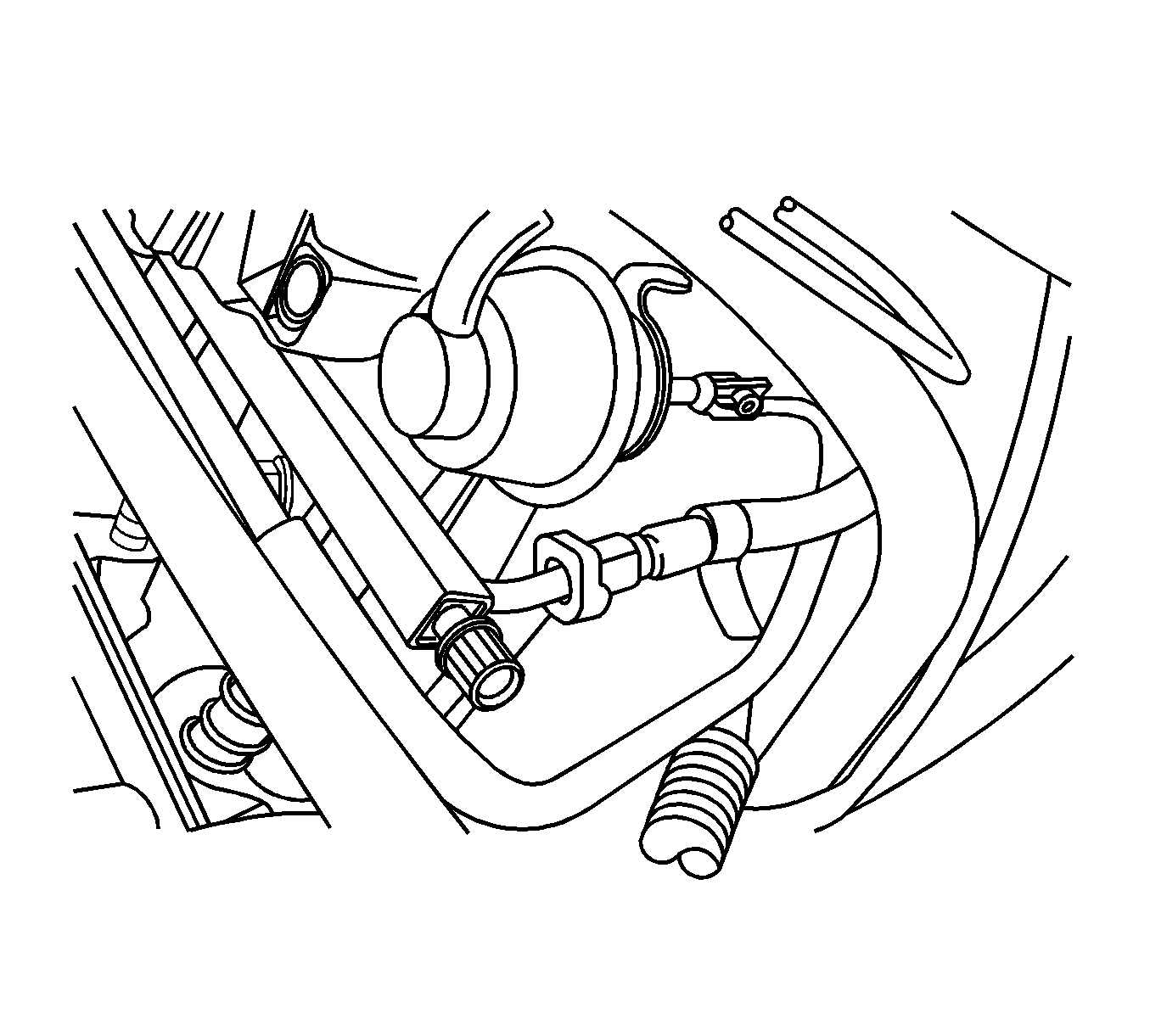
- Remove the purge solenoid valve to intake manifold hose.
- Remove the MAP sensor vacuum hose.
- Remove the upper intake manifold bracket bolts.
- Remove the upper intake manifold bracket.
- Disconnect the fuel feed line.
- Disconnect the throttle body outlet coolant hose.
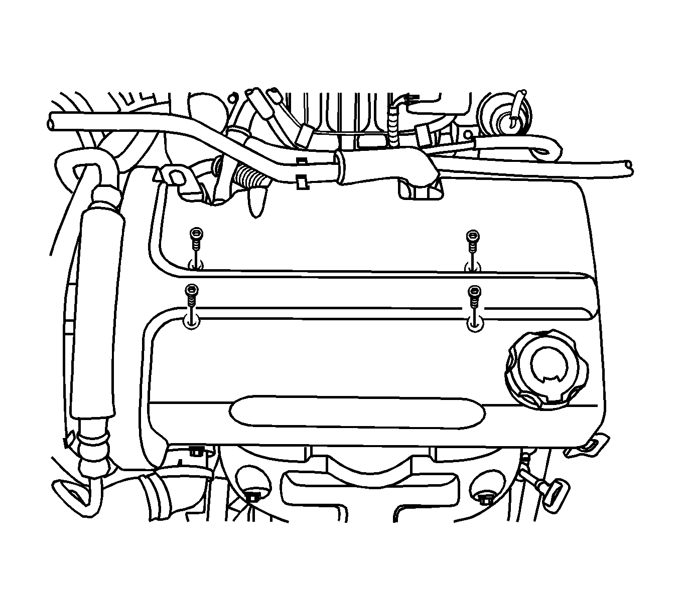
- Remove the fuel rail mounting bolts.
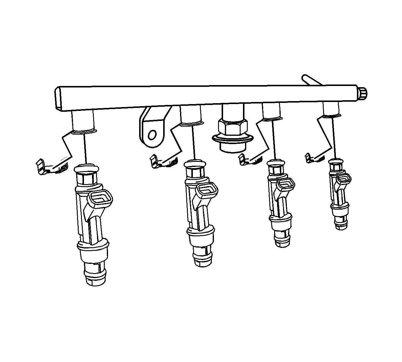
- Remove the fuel rail with the fuel injectors attached.
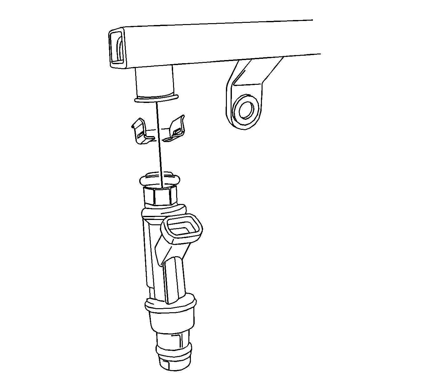
- Remove the fuel injector retaining clips.
- Remove the fuel injectors by pulling down and out.
- Discard the fuel injector O-rings.
Caution: Refer to Relieving Fuel Pressure Caution in the Preface section.
Caution: Refer to Battery Disconnect Caution in the Preface section.
Notice:
• Use care when servicing the fuel system components, especially
the fuel injector electrical connectors, the fuel injector tips, and
the injector O-rings. Plug the inlet and the outlet ports of the fuel rail
in order to prevent contamination. • Do not use compressed air to clean the fuel rail assembly as this
may damage the fuel rail components. • Do not immerse the fuel rail assembly in a solvent bath in order
to prevent damage to the fuel rail assembly.
Important: If an injector becomes separated from the rail and remains in the cylinder head, replace the injector O-ring seals and the retaining clip.
Installation Procedure
- Lubricate the new fuel injector O-rings with engine oil. Install the new O-rings on the fuel injectors.
- Install the fuel injectors into the fuel rail sockets with the fuel injector terminals facing outward.
- Install the fuel injector retainer clips onto the fuel injectors and the fuel rail ledge.
- Make sure that the clip is parallel to the fuel injector harness connector.
- Install the fuel rail assembly into the cylinder head.
- Install the fuel rail mounting bolts.
- Connect the throttle body coolant hose.
- Connect the fuel feed hose.
- Install the intake manifold upper bracket with the bolts.
- Install the MAP sensor vacuum hose.
- Install the purge solenoid to intake manifold hose.
- Connect the fuel injector harness connectors. Rotate each fuel injector as required to avoid stretching the wiring harness.
- Connect the MAP sensor connector.
- Connect the Camshaft position sensor.
- Connect the intake air temperature sensor.
- Connect the electronic throttle control connector.
- Install the engine cover with bolts.
- Connect the negative battery cable.
- Perform a leak check of the fuel rail and fuel injectors.
Important: Different injectors are calibrated for different flow rates. When ordering new fuel injectors, be certain to order the identical part number that is inscribed on the old injector.
Notice: Refer to Fastener Notice in the Preface section.
Tighten
Tighten the fuel rail mounting bolts to 25 N·m (18 lb ft).
