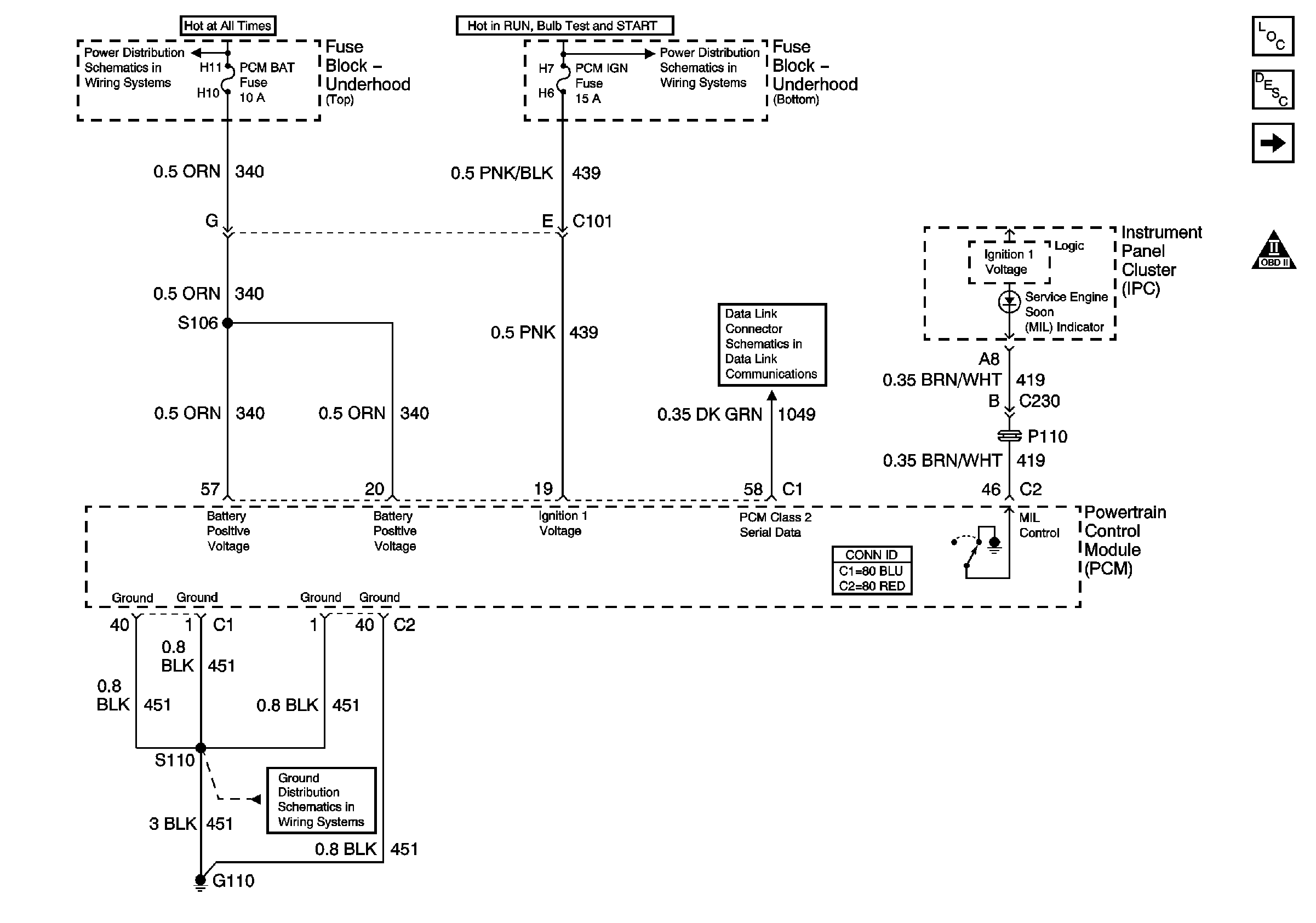
| Figure 1: |
Module Power, Ground, Serial Data and MIL
|
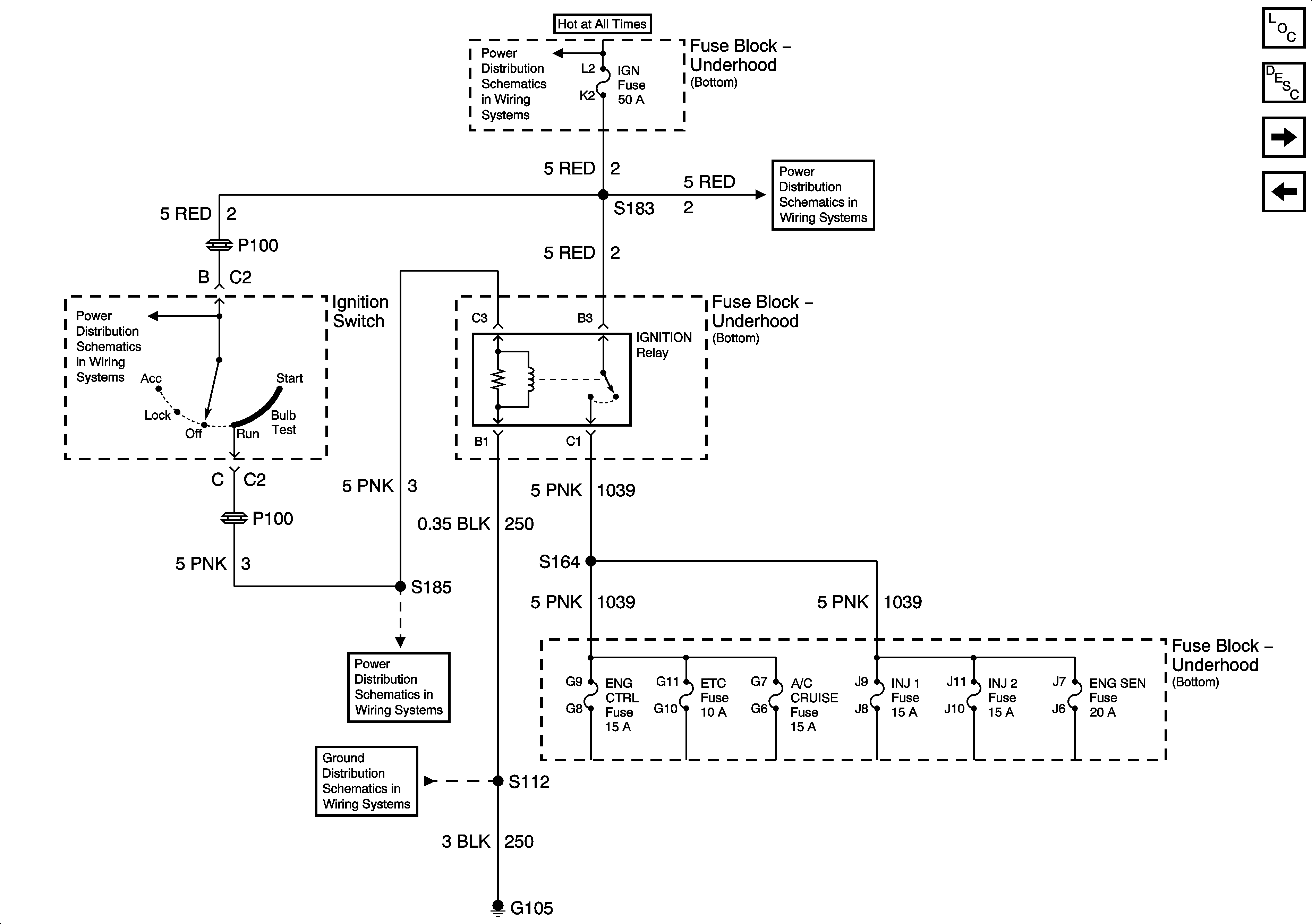
| Figure 2: |
Ignition Relay
|
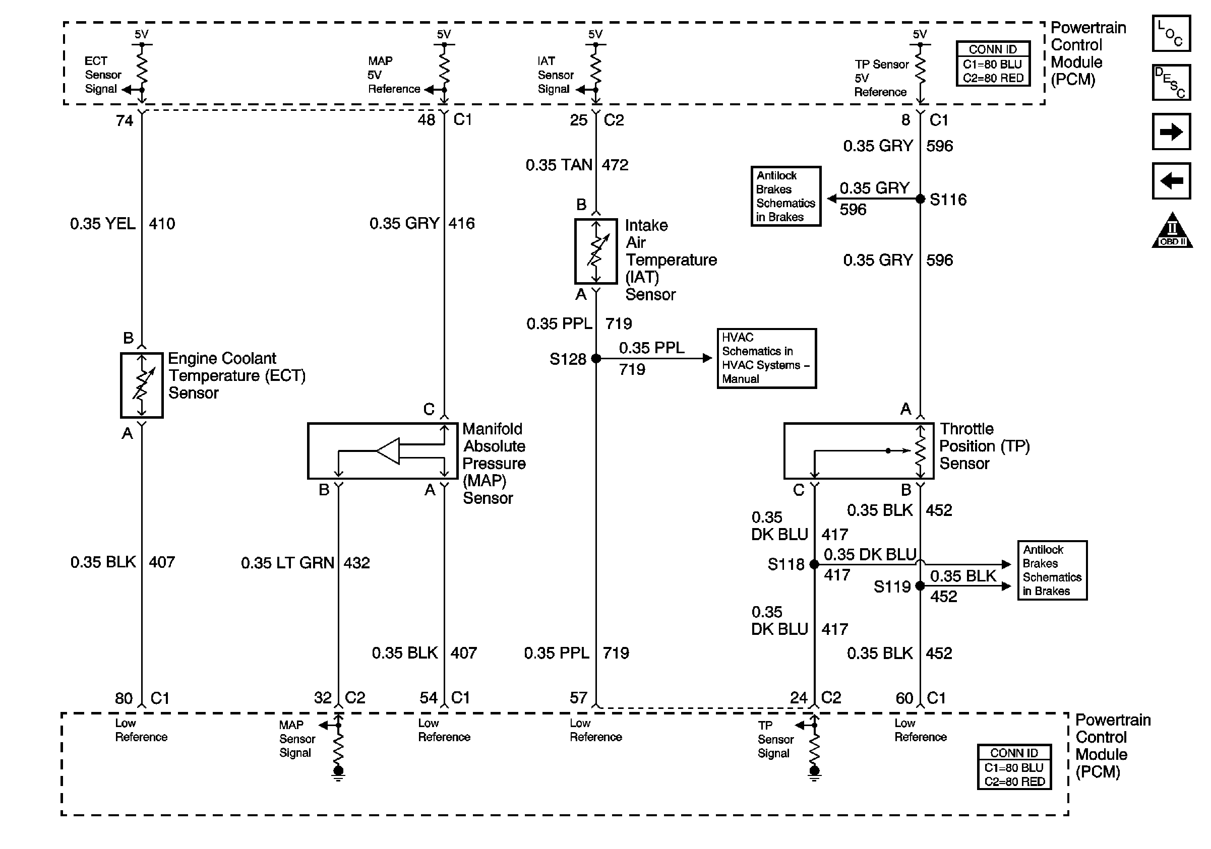
| Figure 3: |
Engine Data Sensors - 5 Volt and Low Reference
|
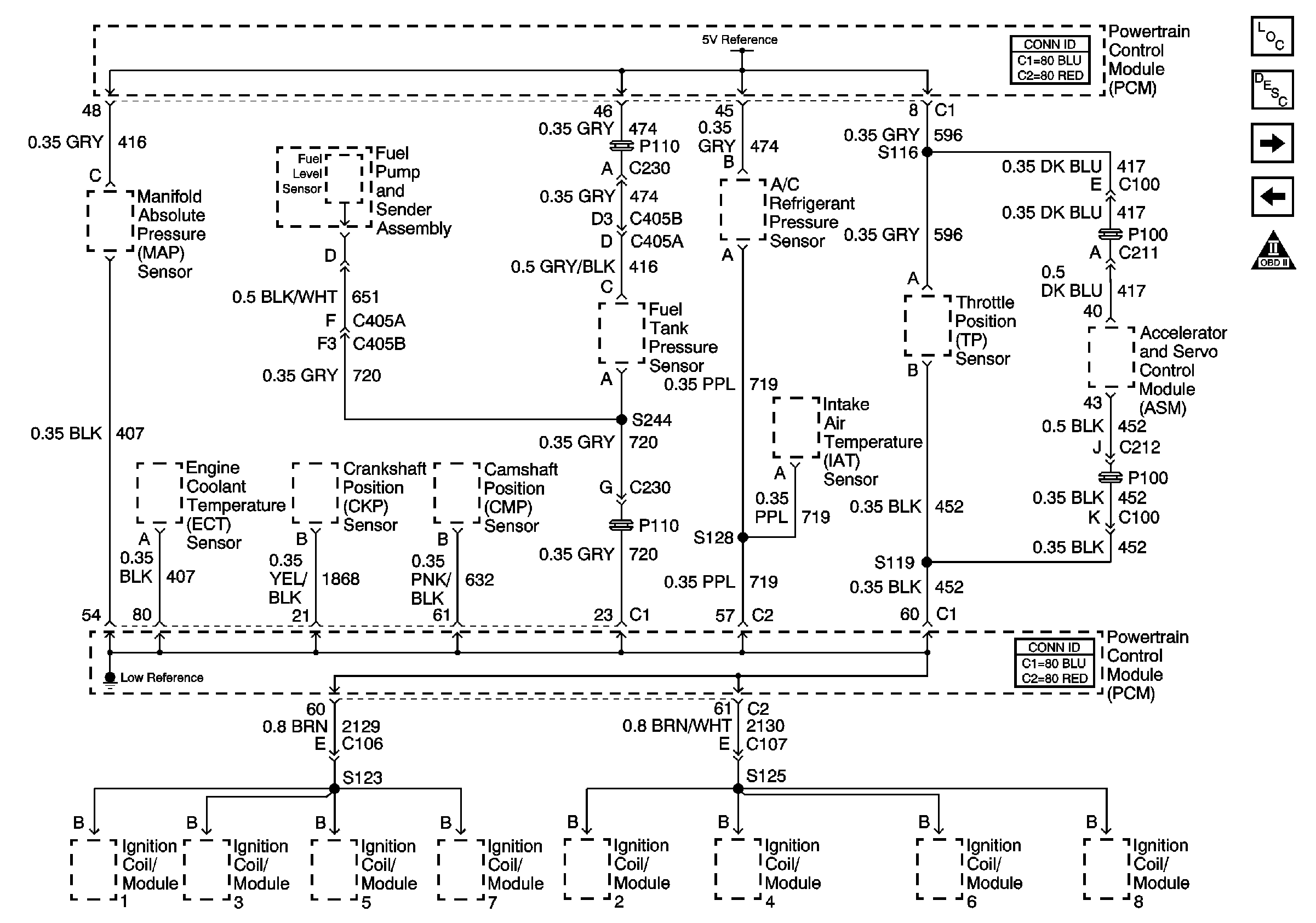
| Figure 4: |
Engine Data Sensors Pressure and Temperature
|
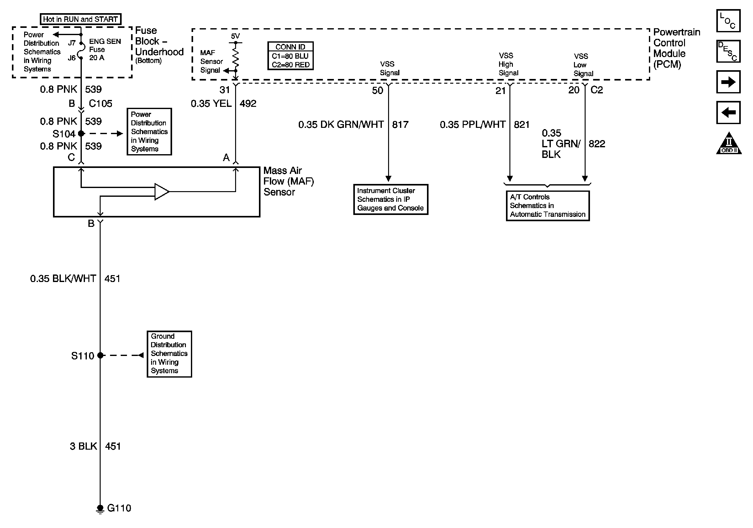
| Figure 5: |
Engine Data Sensors MAF and VSS
|
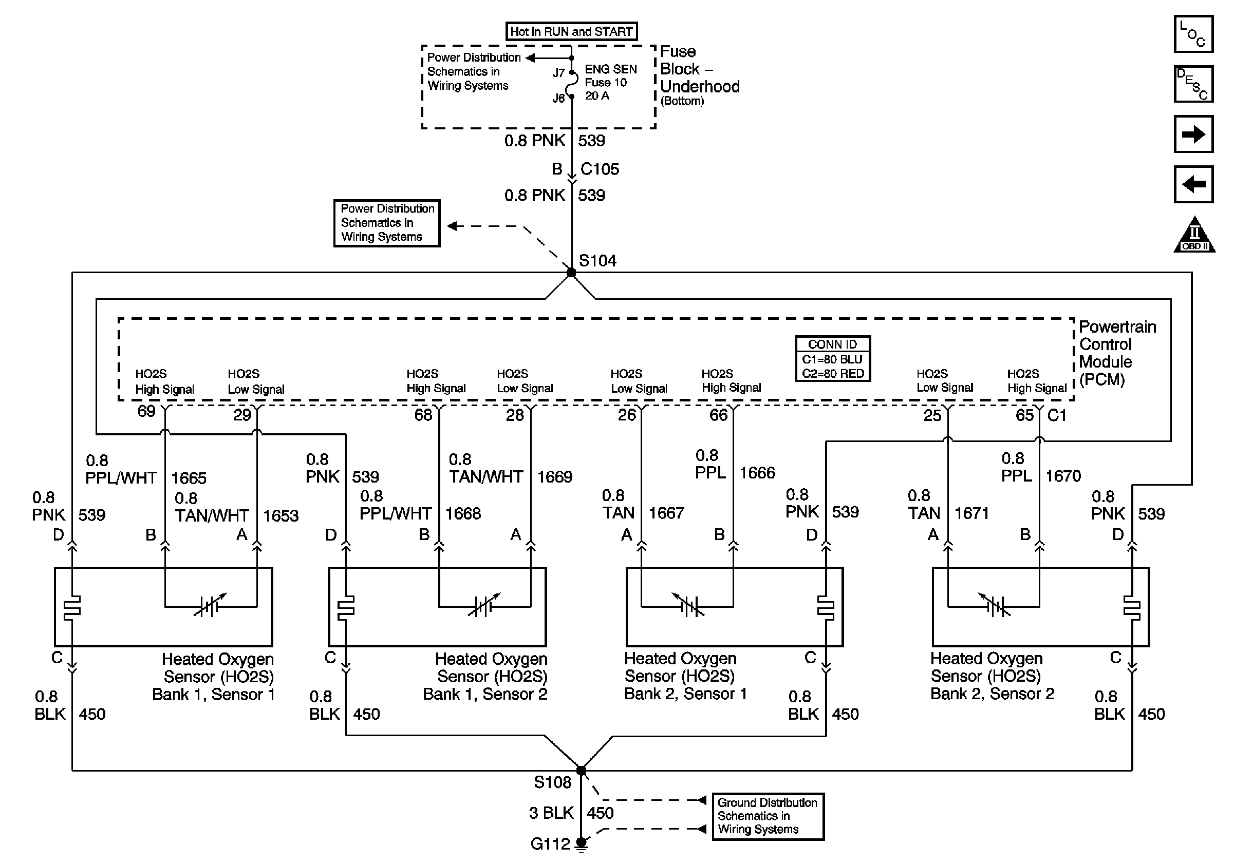
| Figure 6: |
Engine Data Sensors H02S
|
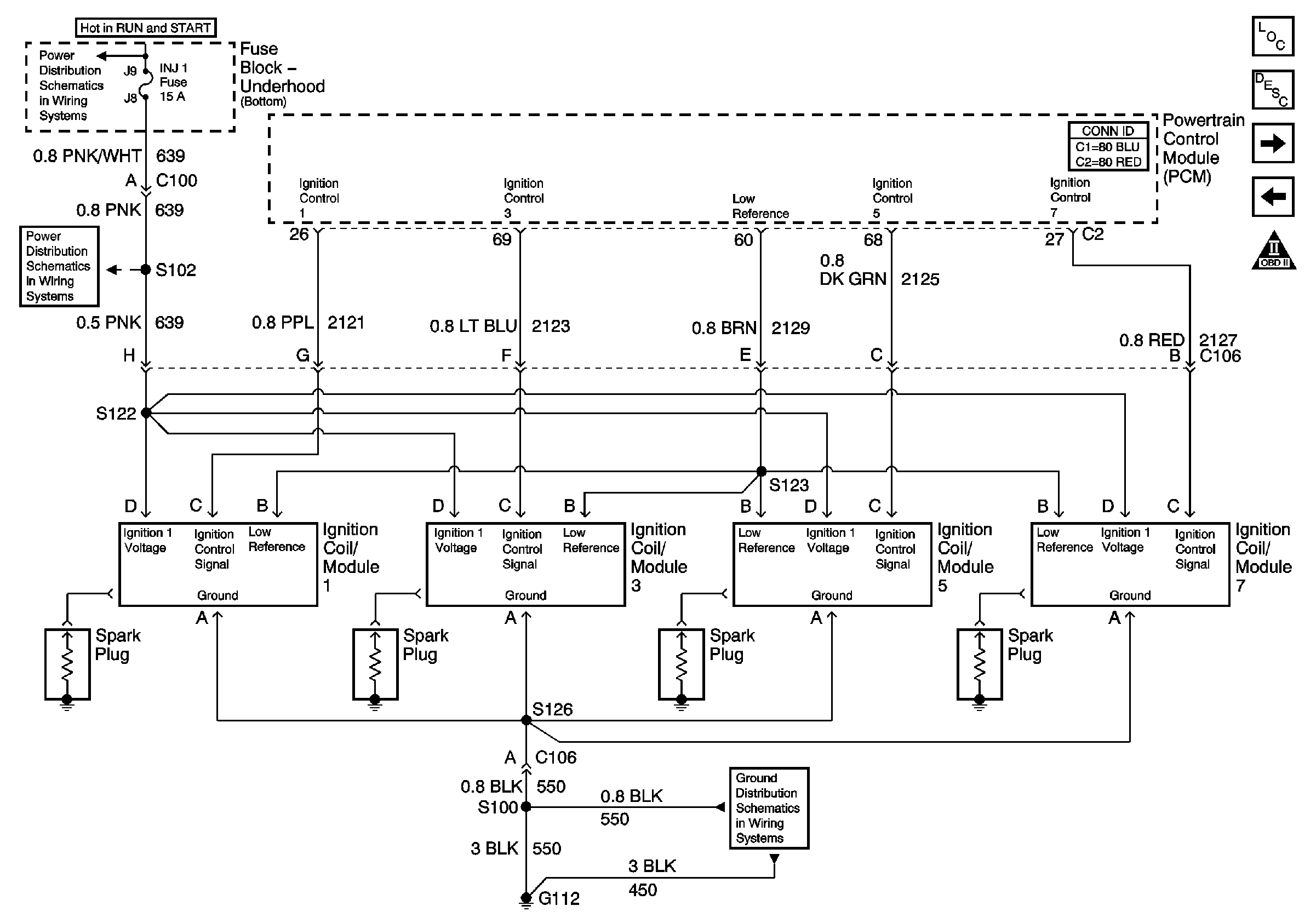
| Figure 7: |
Ignition Controls Ignition System 1,3,5,7
|
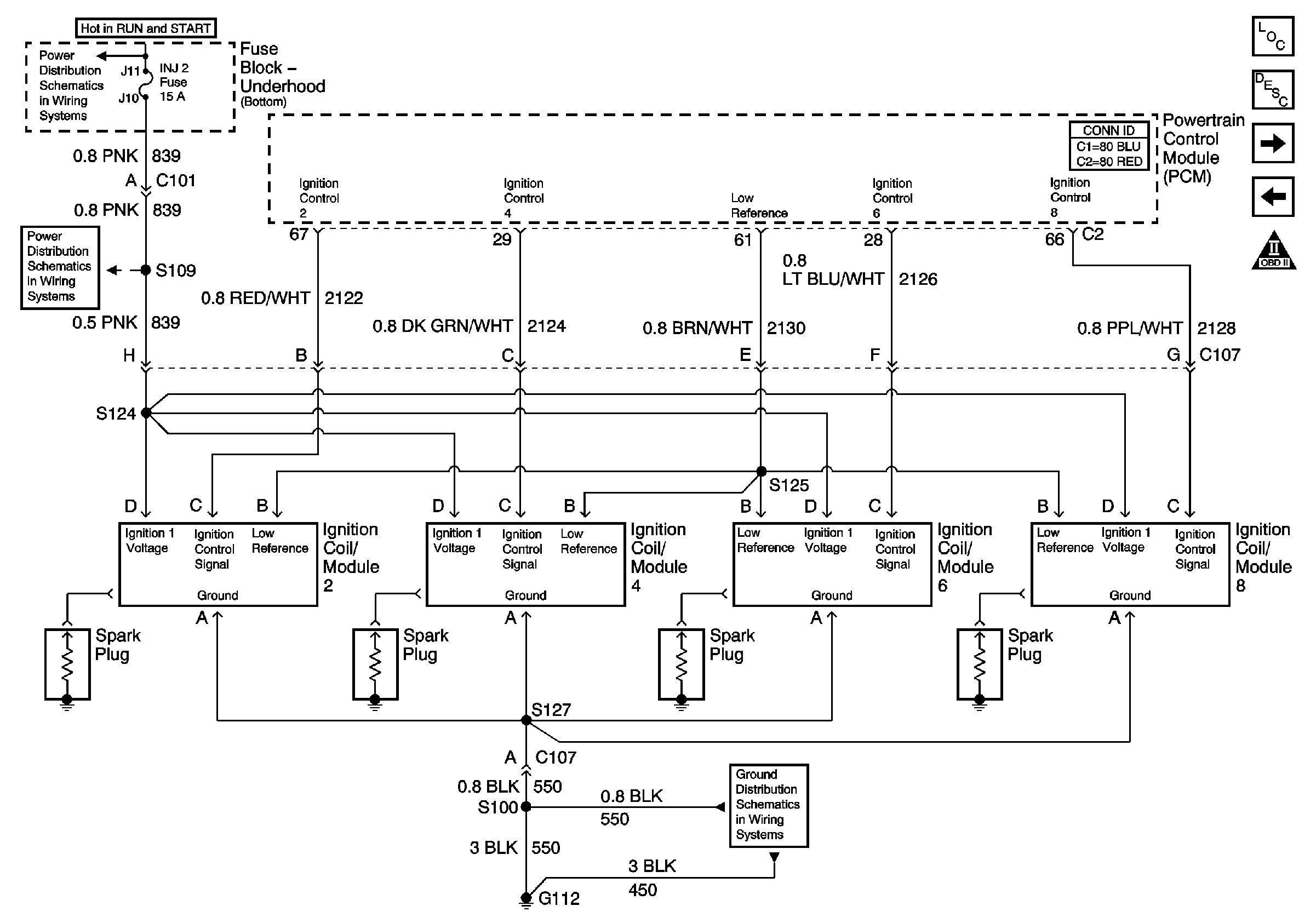
| Figure 8: |
Ignition Controls Ignition System 2,4,6,8
|
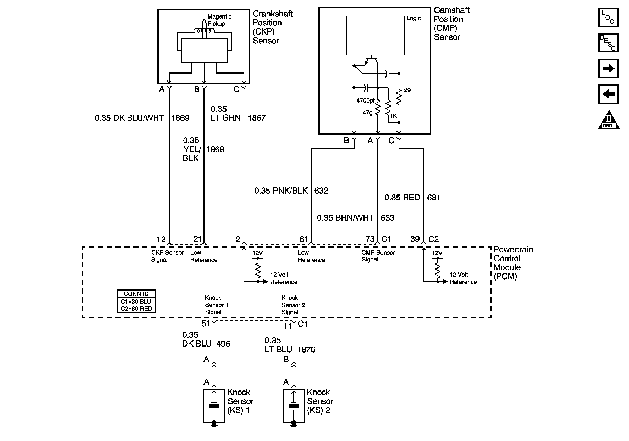
| Figure 9: |
Ignition Controls Sensors
|
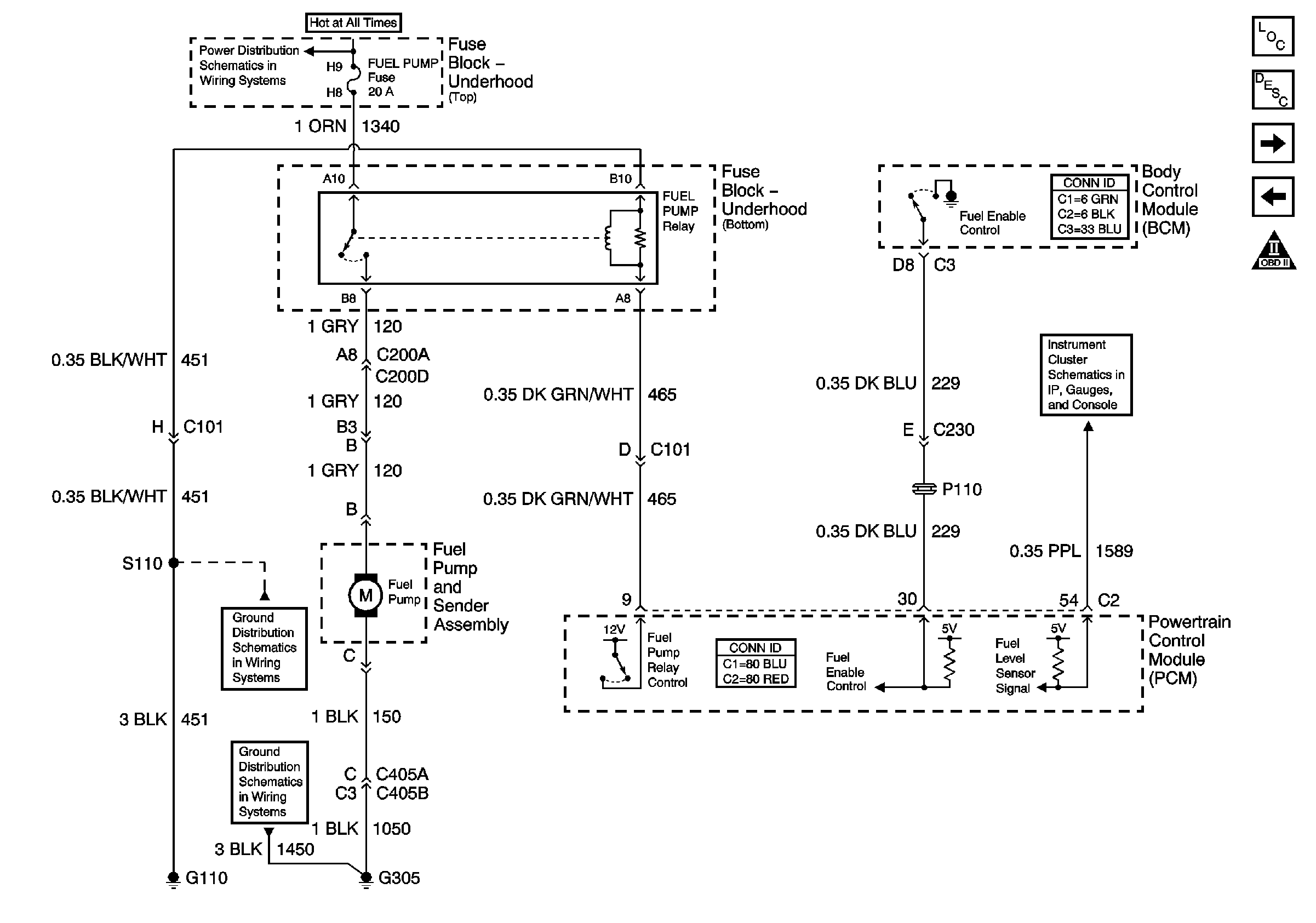
| Figure 10: |
Fuel Controls Fuel Pump Controls
|
| Figure 11: |
Fuel Controls Fuel Injectors

|
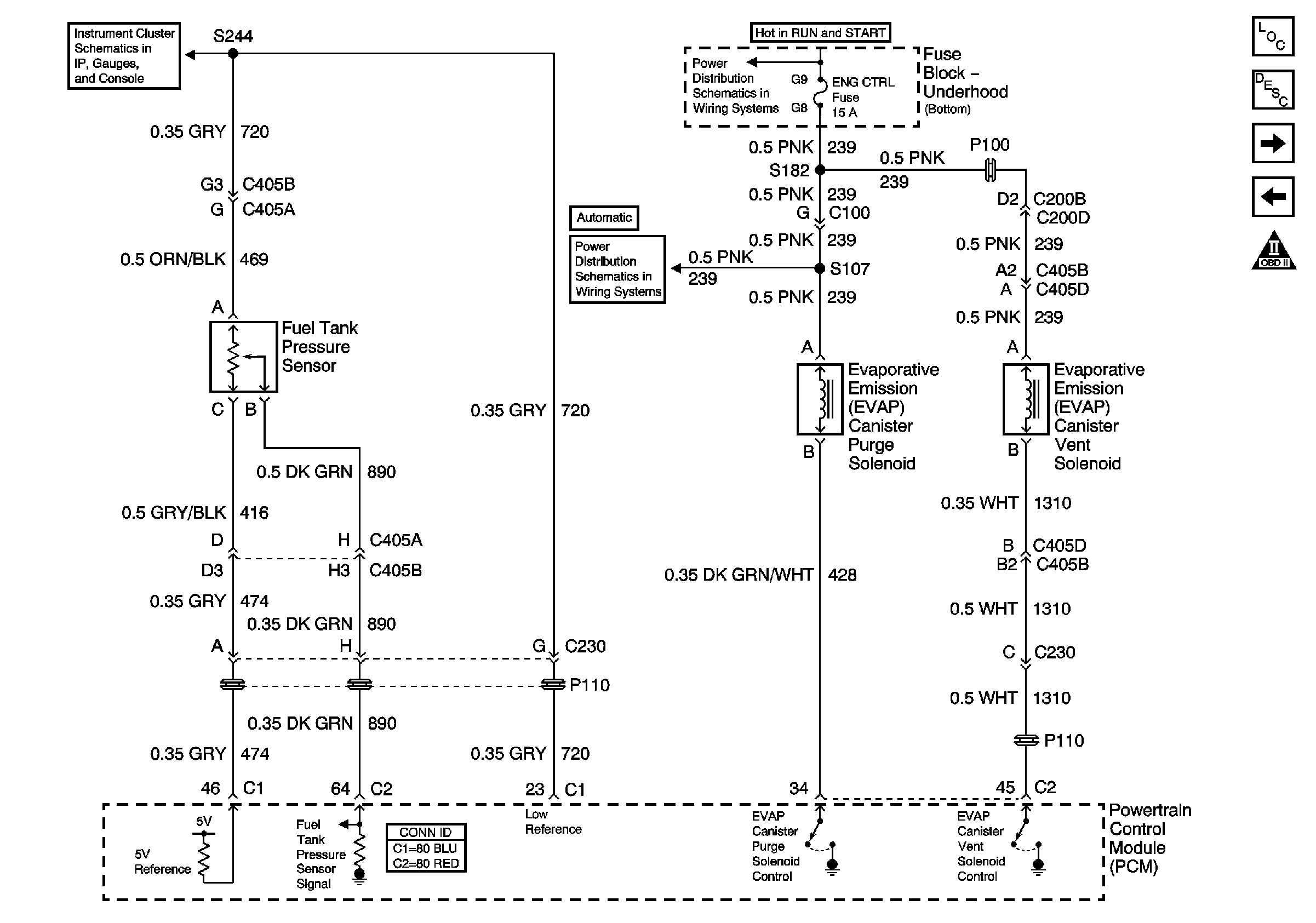
| Figure 12: |
Fuel Controls EVAP Controls
|
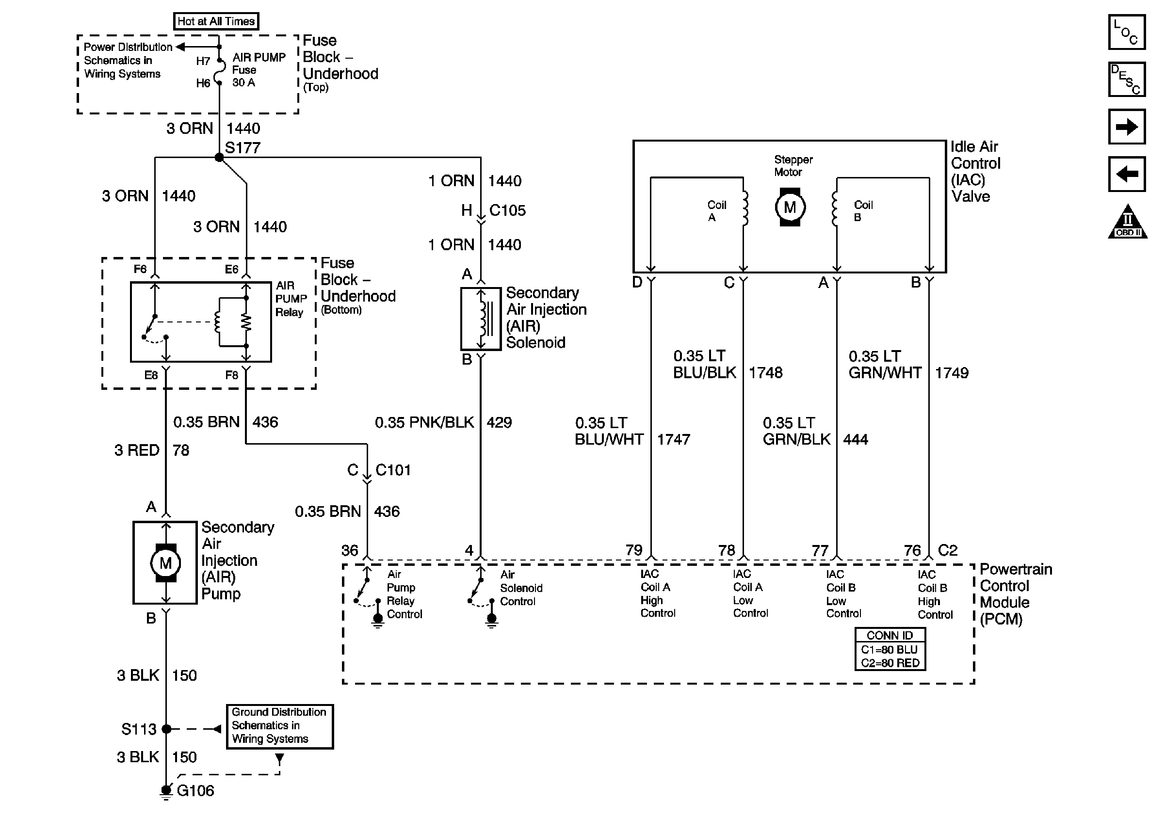
| Figure 13: |
Device Controls
|
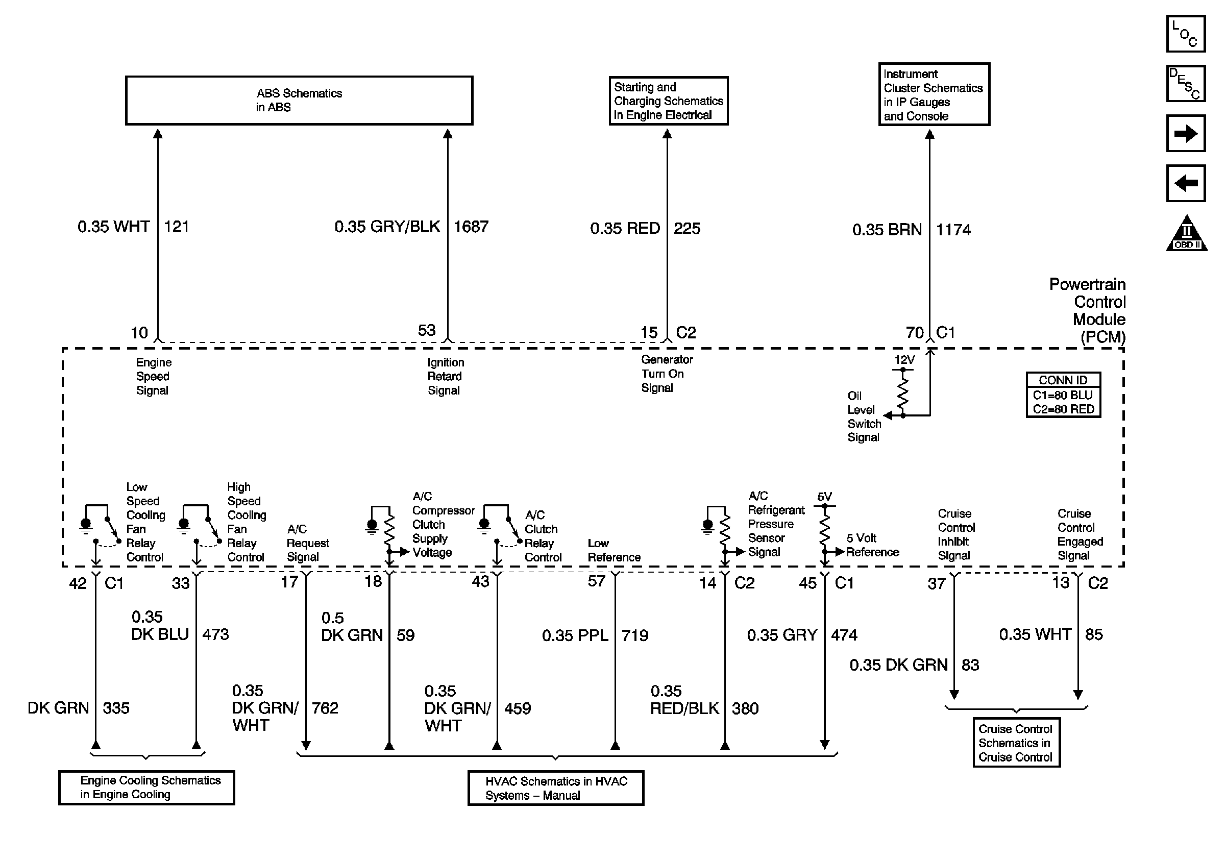
| Figure 14: |
Controlled Monitored Subsystem References
|
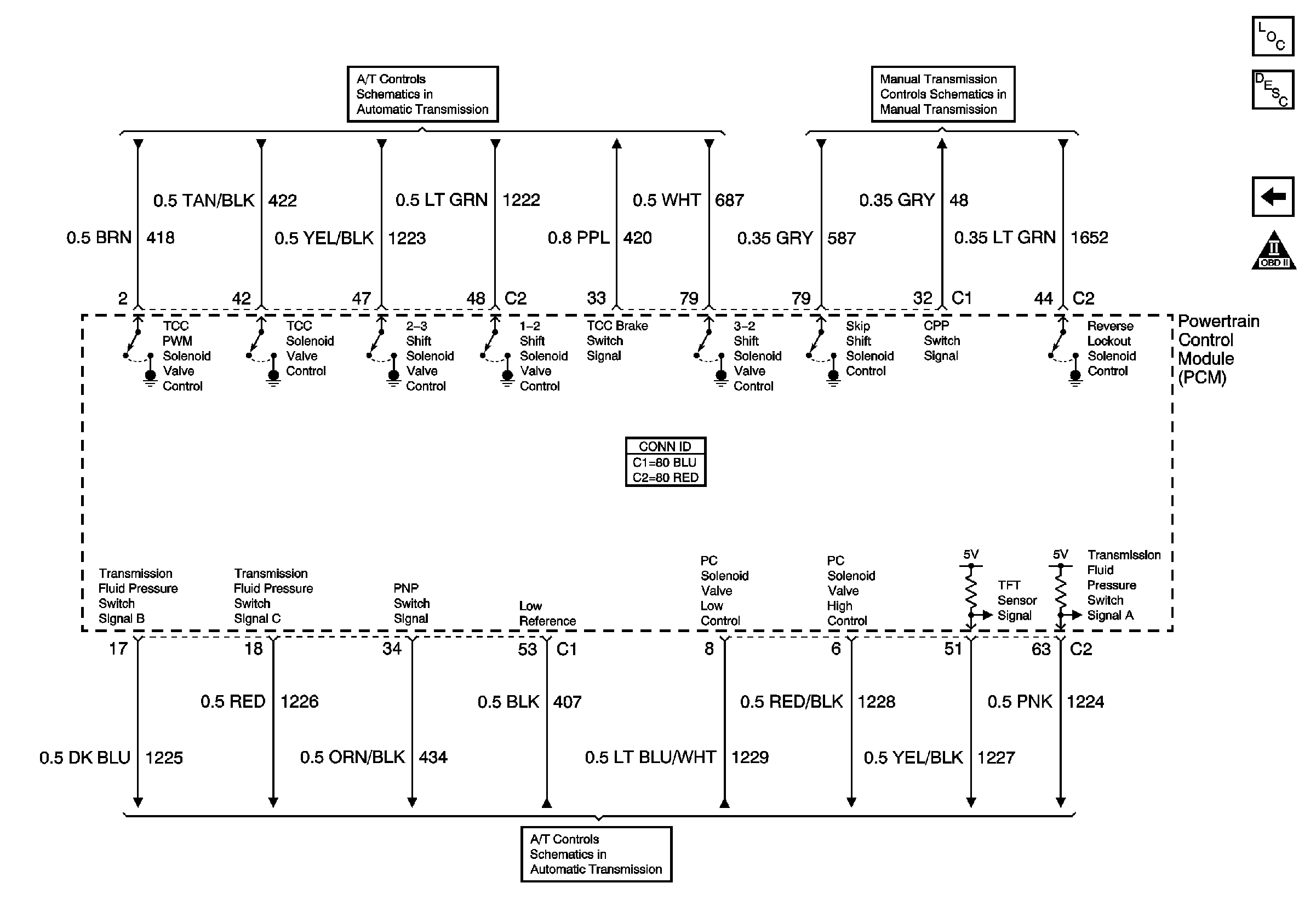
| Figure 15: |
Transmission Controls Manual and Automatic
|
