Removal Procedure
- Remove the driver seat. Refer to Front Seat Replacement - Bucket .
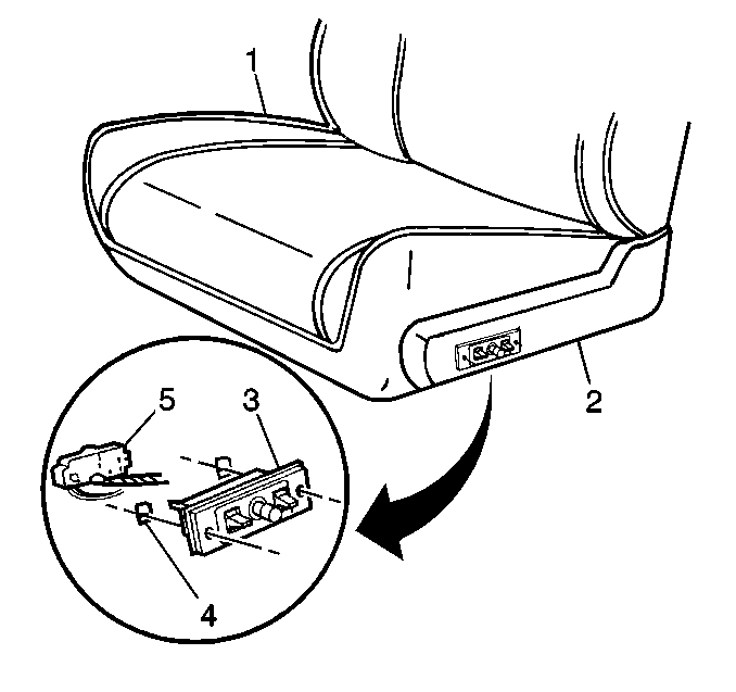
- Remove the hinge arm trim cover. Refer to Hinge Arm Trim Cover.
- Remove the connector (5) from the adjuster (3) by releasing the retainers (4).
Installation Procedure
- Connect the connector (5) to the adjuster (3) by engaging the retainers (4).
- Install the hinge arm trim cover. Refer to Hinge Arm Trim Cover.
- Install the driver seat. Refer to Front Seat Replacement - Bucket .
Adjustment Procedure
With the seat adjuster installed, chucking or jerking can be corrected by tightening or loosening the horizontal actuator and pinion gear to the adjuster lower track rack gear.
- Operate the seat to a 3/4-forward position.
- Loosen the bolt (1).
- Perform the following steps at the same time.
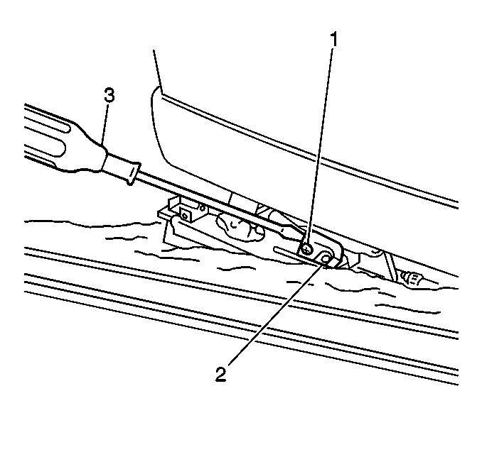
| 3.1. | Use a large screwdriver in order to apply 67-111 N·m (15-25 lb ft) of outward pressure on the actuator (2). |
| 3.2. | Use the horizontal adjuster switch to move the seat forward and backward. |
This will help position and secure the horizontal actuator pinion gear teeth to the lower track rack gear teeth, eliminating any free play.
Notice: Use the correct fastener in the correct location. Replacement fasteners must be the correct part number for that application. Fasteners requiring replacement or fasteners requiring the use of thread locking compound or sealant are identified in the service procedure. Do not use paints, lubricants, or corrosion inhibitors on fasteners or fastener joint surfaces unless specified. These coatings affect fastener torque and joint clamping force and may damage the fastener. Use the correct tightening sequence and specifications when installing fasteners in order to avoid damage to parts and systems.
| 3.3. | While keeping pressure on the actuator (2), tighten the bolt (1). |
Tighten
Tighten the bolt to 28 N·m (20 lb ft).
Phase Adjustment Procedure
The adjuster is out of phase when one adjuster reaches either the maximum horizontal or the maximum vertical travel before the other adjuster. An out-of-phase adjuster can occur over time or when the seat is serviced.
- Operate the horizontal adjuster switch until one adjuster reaches a full-forward position.
- Detach the horizontal drive cable from the full-forward adjuster.
- Operate the horizontal adjuster switch until the other adjuster reaches a full-forward position.
- Connect the horizontal drive cable.
- Inspect the horizontal travel.
- Operate the vertical adjuster switch until one adjuster reaches the full-up position at both the front and rear.
- Disconnect both of the front and the rear vertical drive cable from the full-up adjuster.
- Operate the vertical adjuster switch until the other adjuster reaches the full-up position at both the front and the rear.
- Connect the vertical drive cable.
- Inspect the vertical drive cable.
