Circuit Description
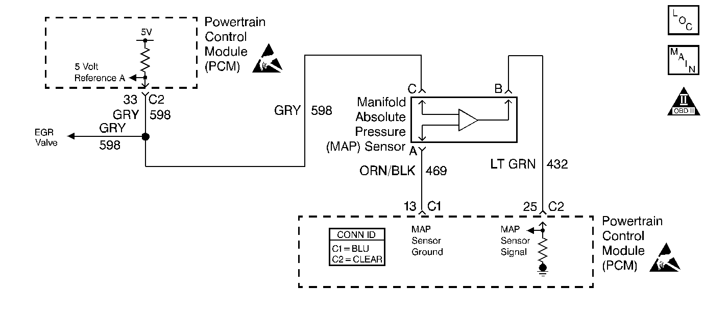
The manifold absolute pressure (MAP) sensor responds to changes in intake manifold pressure (vacuum). The MAP sensor signal voltage to the PCM varies from below 2.0 volts at idle (high vacuum) to above 4.0 volts with the key on, engine not running, or engine running at wide open throttle (low vacuum).
The MAP sensor is used to determine manifold pressure changes while the linear EGR flow test diagnostic is being run to determine engine vacuum level for other diagnostics and to determine barometric pressure (BARO). The PCM monitors the MAP signals for voltages outside the normal range of the MAP sensor. If the PCM detects a MAP signal voltage that is excessively high, DTC P0108 Manifold Absolute Pressure (MAP) Sensor Circuit High Voltage will be set. If the PCM detects a MAP signal voltage that is excessively low, DTC P0107 Manifold Absolute Pressure (MAP) Sensor Circuit Low Voltage will be set.
The PCM also uses the MAP sensor for throttle position sensor performance. If the PCM detects a TP in an out of range condition, when the MAP reading is above or below a calibrated amount then DTC P1514 Throttle Body Performance will be set.
Diagnostic Aids
Inspect for the following:
Many situations may lead to an intermittent condition. Perform each inspection or test as directed.
Important: : Remove any debris from the connector surfaces before servicing a component. Inspect the connector gaskets when diagnosing or replacing a component. Ensure that the gaskets are installed correctly. The gaskets prevent contaminate intrusion.
| • | Loose terminal connection |
| - | Use a corresponding mating terminal to test for proper tension. Refer to Testing for Intermittent Conditions and Poor Connections , and to Connector Repairs in Wiring Systems for diagnosis and repair. |
| - | Inspect the harness connectors for backed out terminals, improper mating, broken locks, improperly formed or damaged terminals, and faulty terminal to wire connection. Refer to Testing for Intermittent Conditions and Poor Connections , and to Connector Repairs in Wiring Systems for diagnosis and repair. |
| • | Damaged harness--Inspect the wiring harness for damage. If the harness inspection does not reveal a problem, observe the display on the scan tool while moving connectors and wiring harnesses related to the sensor. A change in the scan tool display may indicate the location of the fault. Refer to Wiring Repairs in Wiring Systems for diagnosis and repair. |
| • | Inspect the powertrain control module (PCM) and the engine grounds for clean and secure connections. Refer to Wiring Repairs in Wiring Systems for diagnosis and repair. |
If the condition is determined to be intermittent, reviewing the Snapshot or Freeze Frame/Failure Records may be useful in determining when the DTC or condition was identified.
Step | Action | Values | Yes | No | ||||||||||||
|---|---|---|---|---|---|---|---|---|---|---|---|---|---|---|---|---|
1 | Did you perform the Powertrain On-Board Diagnostic System Check? | -- | ||||||||||||||
2 | Inspect for the following conditions:
Did you find and correct the condition? | -- | ||||||||||||||
3 |
Does the scan tool indicate voltage at or near the specified value? | 0.0V | ||||||||||||||
4 |
Does the scan tool indicate voltage at or near the specified value? | 4.95V | ||||||||||||||
5 |
Does the scan tool indicate voltage at or near the specified value? | 4.95V | ||||||||||||||
6 |
Did you find and correct the condition? | -- | ||||||||||||||
7 |
Did you find and correct the condition? | -- | ||||||||||||||
8 |
Did you find and correct the condition? | -- | ||||||||||||||
9 |
Did you find and correct the condition? | -- | ||||||||||||||
10 |
Did you find and correct the condition? | -- | ||||||||||||||
11 | Replace the MAP sensor. Refer to Manifold Absolute Pressure Sensor Replacement . Did you complete the repair? | -- | -- | |||||||||||||
12 | Test the MAP signal circuit for a short to voltage or a short to the 5 volt reference A circuit. Refer to Circuit Testing and Wiring Repairs in Wiring Systems. Did you find and correct the condition? | -- | ||||||||||||||
13 |
Important: : The replacement PCM must be programmed. Replace the PCM. Refer to Powertrain Control Module Replacement/Programming . Did you complete the repair? | -- | -- | |||||||||||||
14 | With a scan tool, observe the MAP parameter while increasing engine RPM. Does the MAP value change? | -- | System OK |
