For complete circuit details refer to
A/C Compressor Control
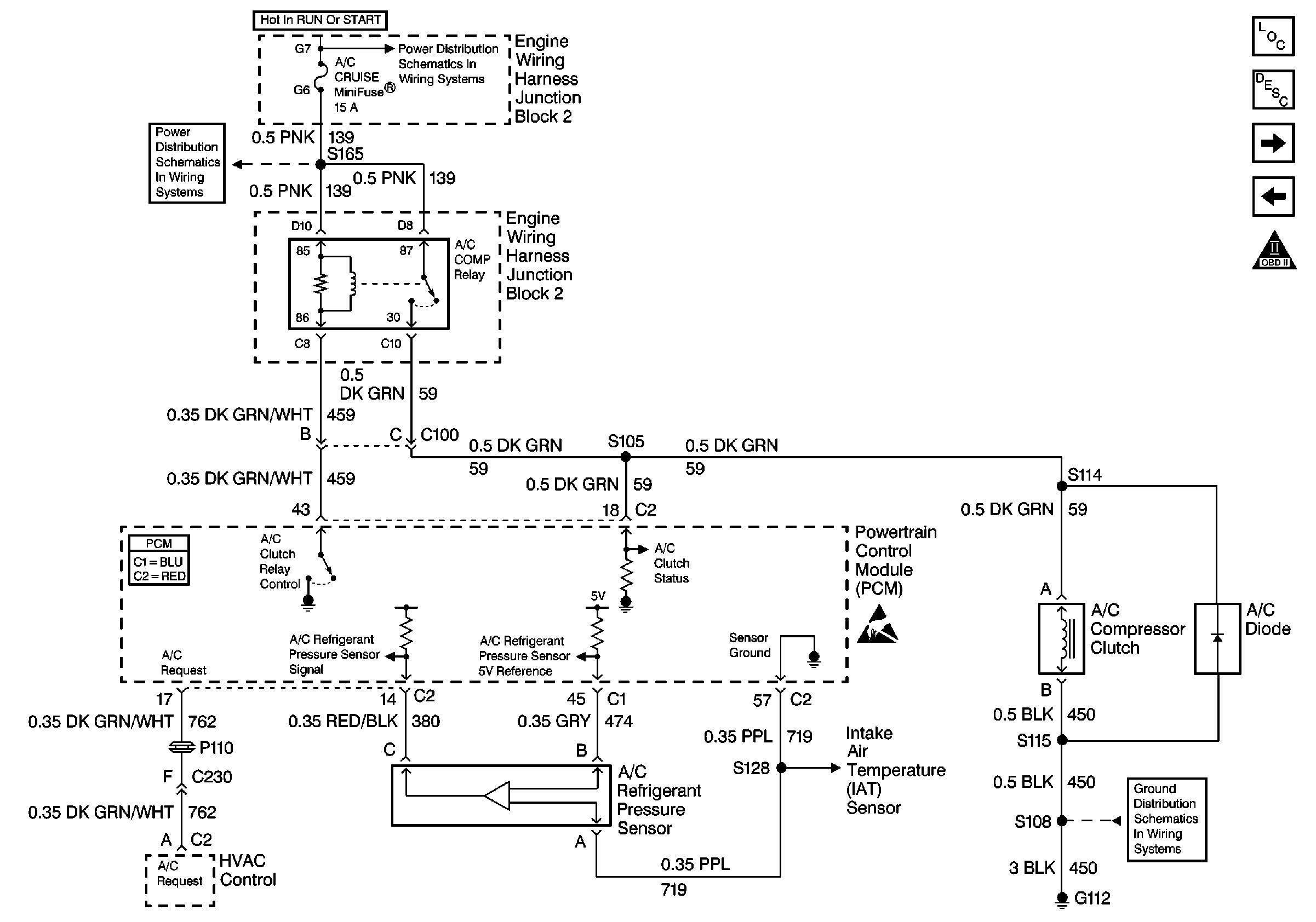
.
Circuit Description:
The A/C clutch relay is PCM controlled to delay A/C clutch engagement after the A/C is turned ON. This allows the PCM to adjust engine RPM before the A/C clutch engages. The PCM will engage the A/C clutch any time A/C has been requested unless any of the following conditions exist:
| • | High coolant temperature |
| • | Low A/C system pressure |
| • | High A/C system pressure |
| • | Wide open throttle |
| • | High engine RPM |
When the heater and A/C control is placed in the A/C mode and the engine is operating, a 12 volt signal is sent to the PCM. When the PCM receives this signal the PCM will ground the A/C clutch relay control circuit to energize the A/C relay. This is shown on the scan tool as A/C request YES.
When a request for A/C has been detected by the PCM, the PCM will ground the A/C clutch relay control circuit, the relay contacts will close, and current will flow through the relay to the A/C compressor clutch.
Diagnostic Aids
Important:
• Remove any debris from the PCM connector surfaces before servicing
the PCM. Inspect the PCM connector gaskets when diagnosing/replacing the PCM.
Ensure that the gaskets are installed correctly. The gaskets prevent water
intrusion into the PCM. • For any test that requires probing the PCM or component harness
connectors, use the J 35616
connector test adapter kit. Using this kit prevents any damage to
the harness connector terminals. Refer to
Using Connector Test Adapters
in Wiring Systems.
Ensure no PCM DTCs are stored before using this table. The PCM will not activate the A/C clutch with a stored DTC.
Test Description
The numbers below refer to numbers on the diagnostic table.
-
A/C DTCs will disable the A/C system. Repair A/C DTCs before proceeding.
-
The request circuit is shorted to a voltage if the scan tool displays A/C request as YES.
-
A condition exists with the request circuit between the PCM and the HVAC Programmer, or the HVAC Programmer is malfunctioning if the test lamp did not illuminate.
Step | Action | Value(s) | Yes | No |
|---|---|---|---|---|
1 | Did you perform the Powertrain On-Board Diagnostic (OBD) System Check? | -- | ||
Are any A/C DTCs set? | -- | Go to the applicable DTC table | ||
Does the scan tool indicate A/C request as YES? | -- | |||
4 | Turn ON the A/C. Does the scan tool indicate A/C request as YES? | -- | System OK | |
Does the DMM display near the specified value when the A/C is enabled? | B+ | |||
6 |
Does the DMM indicate continuity? | -- | ||
7 | Probe the A/C request circuit at the PCM harness connector using the J 35616-200 test lamp connected to B+. Refer to Probing Electrical Connectors in Wiring Systems. Does the test lamp illuminate? | -- | ||
8 |
Did you find and correct the condition? | -- | System OK | |
9 |
Important: Before replacing the HVAC Programmer, refer to Diagnostic Starting Point in HVAC Systems-Manual. Replace the HVAC Programmer. Refer to Control Assembly Replacement in HVAC Systems-Manual. Is the action complete? | -- | System OK | -- |
10 |
Did you find and correct the condition? | -- | System OK | |
11 | Repair the open A/C request circuit between the HVAC Programmer and the PCM. Refer to Wiring Repairs in Wiring Systems. Is the action complete? | -- | System OK | -- |
12 | Repair the grounded A/C request circuit between the HVAC Programmer and the PCM. Refer to Wiring Repairs in Wiring Systems. Is the action complete? | -- | System OK | -- |
13 |
Important:: Program the replacement PCM. Refer to Powertrain Control Module Replacement/Programming Replace the PCM. Is the action complete? | -- | System OK | -- |
