Refer to Engine Controls Schematics,
Cooling Fans
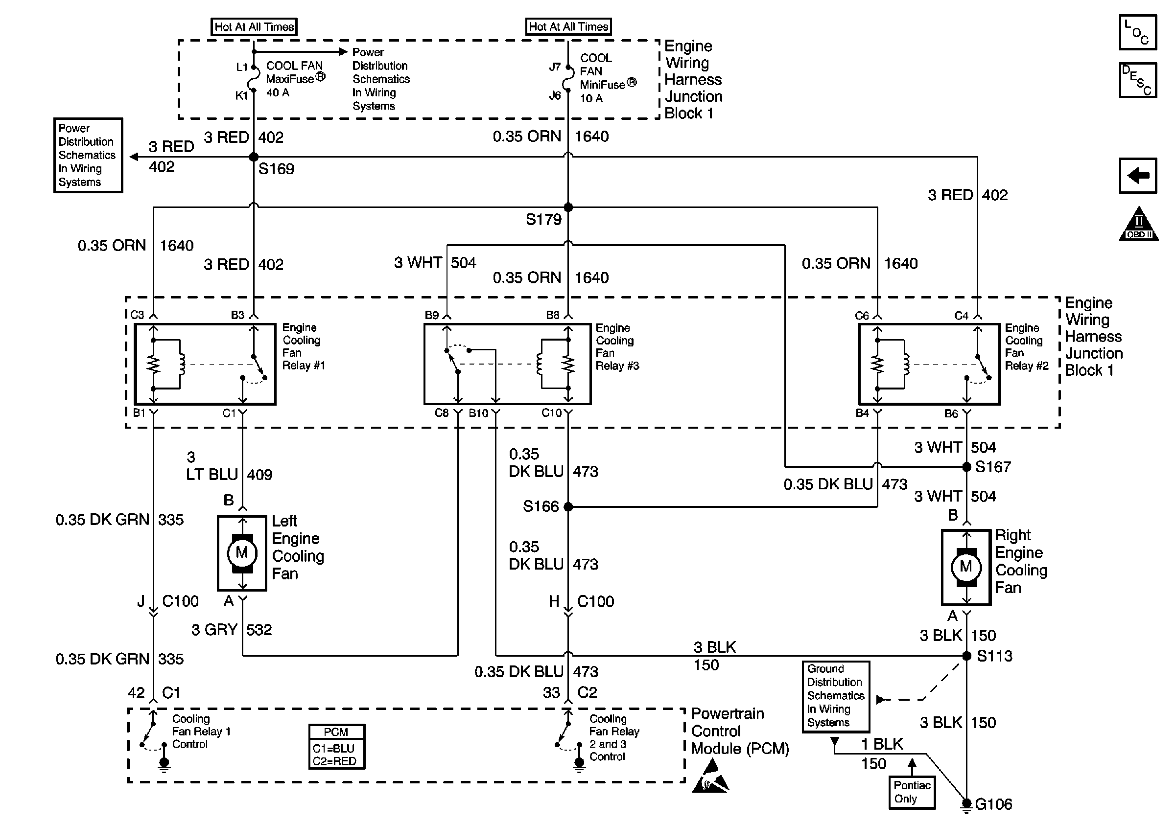
for complete circuit details.
Circuit Description
The cooling fan system in this vehicle provides for two separate modes of operation. These are the low speed fan and the high speed fan operating modes. The low speed mode operates both fans at half speed by using a series circuit configuration. The high speed mode operates both fans at full speed by using a parallel circuit configuration. These two operating modes are accomplished using 3 fan control relays.
This system which uses three relays to control two fan motors appears complicated. To aid in better understanding this system it is suggested to follow the circuits in the schematic as you read the description. This will aid in understanding the two distinct modes of operating the relays and coolant fans.
Low speed fan operation is established when the PCM commands Fan Relay #1 ON by grounding circuit 335 with an internal driver (relays #2 and #3 are left OFF). This closes the relay switch and allows current to flow from the battery, through the switch contacts on circuit 409 to the Left Hand cooling fan. Current flow continues out of the fan motor on circuit 532 to relay #3. The unenergized relay #3 switch contacts allow current to flow to circuit 504. This provides power to the Right Hand cooling fan motor. The low side of the RH cooling fan completes the circuit to ground on circuit 150. This circuit is a series circuit which allows half speed operation for each fan since each fan motor will use half of the supplied battery power.
High speed operation is established when all three relays are energized. Relays #2 and #3 share the same control circuit to the PCM. This is circuit 473. As in the low speed mode, Relay #1 supplies current flow to the LH cooling fan on circuit 409. Current flow continues through the motor on circuit 532 to relay #3 which is now energized. The switch has now provided a path for current to flow through circuit 150 directly to ground. This circuit now only has the LH fan motor to power and allows it to run at full speed. Relay #2 is also energized and provides current flow on circuit 504 to the RH cooling fan. This fan now has its own dedicated circuit and will operate at full speed. This mode is operating as a parallel circuit.
Conditions for Running the DTC
| • | The engine speed is more than 400 RPM. |
| • | The ignition voltage is between 6.0 volts and 18.0 volts. |
Conditions for Setting the DTC
| • | The PCM detects that the commanded state of the driver and the actual state of the control circuit do not match. |
| • | The conditions must be present for a minimum of 5 seconds. |
Action Taken When the DTC Sets
| • | The PCM illuminates the malfunction indicator lamp (MIL) on the second consecutive ignition cycle that the diagnostic runs and fails. |
| • | The PCM records the operating conditions at the time the diagnostic fails. The first time the diagnostic fails, the PCM stores this information in the Failure Records. If the diagnostic reports a failure on the second consecutive ignition cycle, the PCM records the operating conditions at the time of the failure. The PCM writes the conditions to the Freeze Frame and updates the Failure Records. |
Conditions for Clearing the MIL/DTC
| • | The PCM turns OFF the malfunction indicator lamp (MIL) after 3 consecutive ignition cycles that the diagnostic runs and does not fail. |
| • | A last test failed, or current DTC, clears when the diagnostic runs and does not fail. |
| • | A history DTC clears after 40 consecutive warm-up cycles, if no failures are reported by this or any other emission related diagnostic. |
| • | Use a scan tool in order to clear the MIL and the DTC. |
Diagnostic Aids
Important:
• Remove any debris from the PCM connector surfaces before servicing
the PCM. Inspect the PCM connector gaskets when diagnosing/replacing the PCM.
Ensure that the gaskets are installed correctly. The gaskets prevent
water intrusion into the PCM. • For any test that requires probing the PCM or a component
harness connector, use the J 35616
connector test adapter kit. Using this kit prevents damage to
the harness/component terminals. Refer to
Using Connector Test Adapters
in Wiring Systems.
For an intermittent, refer to Symptoms .
Test Description
The numbers below refer to the step numbers on the diagnostic table.
-
Listen for an audible click when the relay operates. Command both the ON and the OFF states. Repeat the commands as necessary.
-
This step tests for voltage at the coil side of the cooling fan relay 1. The cooling fan mini fuse supplies power to the coil side of the cooling fan relay 1.
-
This step verifies that the PCM is providing ground to the cooling fan relay 1.
-
This step tests if ground is constantly being applied to the cooling fan relay.
Step | Action | Value(s) | Yes | No |
|---|---|---|---|---|
1 | Did you perform the Powertrain On-Board Diagnostic (OBD) System Check? | -- | ||
Does the cooling fan relay turn ON and OFF with each command? | -- | |||
3 |
Does the DTC reset? | -- | Go to Intermittent Conditions | |
Does the test lamp illuminate? | -- | |||
Does the test lamp turn ON and OFF with each command? | -- | |||
Does the test lamp remain illuminated with each command? | -- | |||
7 |
Did you find and correct the condition? | -- | ||
8 |
Did you find and correct the condition? | -- | ||
9 |
Did you find and correct the condition? | -- | ||
10 |
Did you find and correct the condition? | -- | ||
11 | Repair the coil side feed circuit of the cooling fan relay. Refer to Wiring Repairs in Wiring Systems. Did you complete the repair? | -- | -- | |
12 | Replace the cooling fan relay 1. Is the action complete? | -- | -- | |
13 |
Important: Program the replacement PCM. Refer to Powertrain Control Module Replacement/Programming . Replace the PCM. Is the action complete? | -- | -- | |
14 |
Does the DTC reset? | -- | ||
15 | With a scan tool, review the Stored Information (capture info). Does the scan tool display any DTCs that you have not diagnosed? | -- | System OK |
