Refer to Engine Controls Schematics,
Fuel Injectors
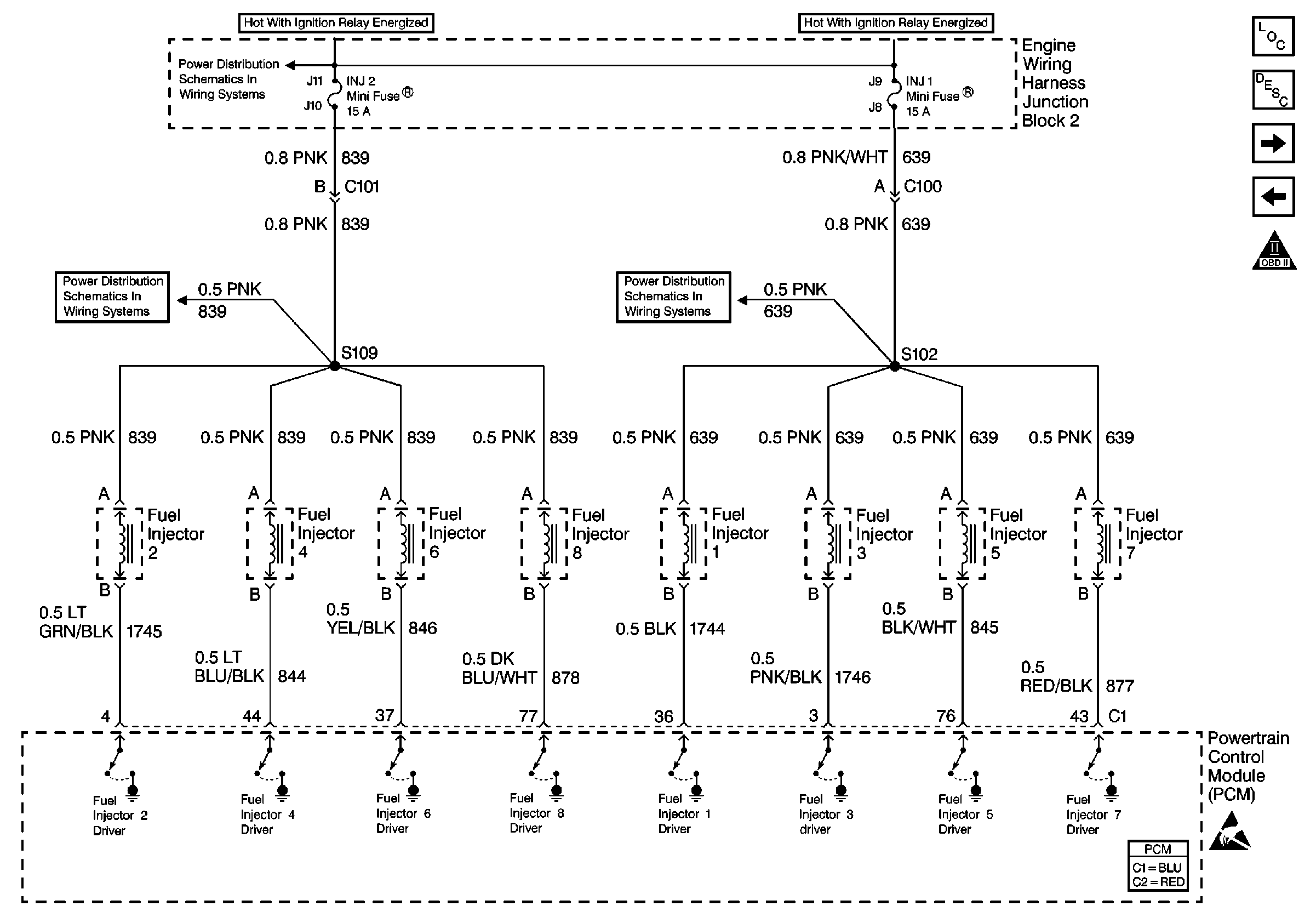
for complete circuit details.
Circuit Description
The PCM enables an injector on the intake stroke of each cylinder. Individual cylinder fuel control is referred to as Sequential Multi-port Fuel Injection (SFI).
Ignition voltage is supplied directly to the fuel injectors. The PCM controls each injector by grounding the control circuit via an internal switch called a driver. The primary function of the driver is to supply the ground for the component being controlled. Each driver or control circuit is equipped with a fault line which is monitored by the PCM. When the PCM is commanding an injector ON, the voltage of the control circuit should be low. When the PCM is commanding the injector OFF, the voltage potential of the control circuit should be high. If the PCM detects the injector control circuit voltage other than what is expected, the PCM sets a DTC.
Conditions for Running the DTC
| • | The engine speed is more than 400 RPM. |
| • | The ignition voltage is more than 6.0 volts but less than 18.0 volts. |
Conditions for Setting the DTC
The PCM detects the wrong voltage potential on any injector driver circuit for 5 seconds.
Action Taken When the DTC Sets
| • | The PCM illuminates the malfunction indicator lamp (MIL) on the second consecutive ignition cycle that the diagnostic runs and fails. |
| • | The PCM records the operating conditions at the time the diagnostic fails. The first time the diagnostic fails, the PCM stores this information in the Failure Records. If the diagnostic reports a failure on the second consecutive ignition cycle, the PCM records the operating conditions at the time of the failure. The PCM writes the conditions to the Freeze Frame and updates the Failure Records. |
Conditions for Clearing the MIL/DTC
| • | The PCM turns OFF the malfunction indicator lamp (MIL) after 3 consecutive ignition cycles that the diagnostic runs and does not fail. |
| • | A last test failed, or current DTC, clears when the diagnostic runs and does not fail. |
| • | A history DTC clears after 40 consecutive warm-up cycles, if no failures are reported by this or any other emission related diagnostic. |
| • | Use a scan tool in order to clear the MIL and the DTC. |
Diagnostic Aids
Important:
• Remove any debris from the PCM connector surfaces before servicing
the PCM. Inspect the PCM connector gaskets when diagnosing/replacing the PCM.
Ensure that the gaskets are installed correctly. The gaskets prevent
contaminant intrusion into the PCM. • For any test that requires probing the PCM or component
harness connectors, use the J 35616
connector test adapter kit. Using this kit prevents
any damage to the harness connector terminals. Refer
to
Using Connector Test Adapters
in Wiring Systems.
A misfire may not be apparent at idle. The misfire may only occur above idle under a load. Road test the vehicle and monitor the misfire current counters.
Observe, if more than one cylinder is mis-firing, the scan tool may only display one cylinder mis-firing. This will not be apparent until the repair is completed. Also, if an injector fuse is open for one side of the engine, the scan tool may only display 2 or 3 cylinders mis-firing.
When the injector driver is disabled, an engine misfire will be apparent and a misfire DTC sets.
For an intermittent condition, refer to Symptoms .
Test Description
The numbers below refer to step numbers on the diagnostic table.
-
This step determines if a malfunction is present.
The Misfire Current Counters will not increment if certain DTCs set at the same time or after DTC P0300 sets. Refer to conditions for running DTC P0300 for applicable DTC list.
If more than one cylinder is misfiring, the Misfire Current Counters may increment for only one cylinder. Example: Cylinders 1 and 8 are both misfiring, yet only cylinder 8 increments on the Misfire Current Counter.
If one injector fuse open, only two or three Misfire current counters may increment for the corresponding side of the engine.
-
There are two ways to isolate a malfunctioning injector circuit:
-
The injector fuses also feed the ignition coil/modules. Thoroughly inspect the circuits going to the ignition coil/modules for a short to ground. A shorted ignition coil/module may also cause a fuse to open.
-
Inspect the injector connections before replacing the injector. A faulty connection causes an inoperative injector.
-
Disconnecting the PCM allows testing the continuity of the circuits with the DMM. This aids in locating an open or shorted circuit. Tests for an ignition feed circuit that is shorted to ground.
-
Tests for an ignition feed circuit that is shorted to ground.
-
The injector fuses also feed the ignition coil/modules. Thoroughly inspect the circuits going to the ignition coil/modules for a short to ground. A shorted ignition coil/module may also cause a fuse to open.
| • | DTC P0300 indicates a misfire is present. So use the Misfire Current Counters to locate the cylinder that is misfiring. |
| • | If no misfire DTC is present, Start and idle the engine while monitoring Misfire Current Counters. If a misfire is present, the Misfire Current Counters will increase for a cylinder that has a misfire. |
Step | Action | Value(s) | Yes | No | ||||||
|---|---|---|---|---|---|---|---|---|---|---|
1 | Did you perform the Powertrain On-Board Diagnostic (OBD) System Check? | -- | ||||||||
Are any of the Misfire Current Counters incrementing? | -- | |||||||||
Monitor the Misfire History Counters on the Misfire Data List (There are a total of 8 counters. One counter per cylinder) with a scan tool. Do any of the Misfire History Counters indicate a number other than 0.0 counts? | -- | Go to Diagnostic Aids | ||||||||
Are the injector fuses OK? | -- | |||||||||
5 |
Does the test lamp illuminate? | -- | ||||||||
6 |
Does the injector test lamp blink? | -- | ||||||||
Did you find and correct the condition? | -- | |||||||||
8 |
Does the test lamp illuminate? | -- | ||||||||
9 |
Important: Return to this Diagnostic after performing the Fuel Injector Coil Test. Perform the Fuel Injector Coil Test. Refer to Fuel Injector Solenoid Coil Test - Engine Coolant Temperature Between 10-35 Degrees C (50-95 Degrees F) . Did the Fuel Injector Coil Test isolate an injector condition? | -- | ||||||||
10 | Repair the injector ignition feed circuit to the isolated injector. Refer to Wiring Repairs in Wiring Systems. Is the action complete? | -- | -- | |||||||
|
Important: Disconnecting the PCM may eliminate the short to ground, or short to voltage if the injector circuit is shorted to another PCM circuit.
Is the injector control circuit open or shorted? | -- | |||||||||
12 | Repair the injector control circuit for an open, short to ground, or a short to voltage. Refer to Wiring Repairs in Wiring Systems. Is the action complete? | -- | -- | |||||||
Is the action complete? | -- | -- | ||||||||
Repair the intermittent short to ground in the injector ignition feed circuit. Refer to Wiring Repairs in Wiring Systems. Is the action complete? | -- | -- | ||||||||
15 | Replace the faulty injector(s) that was isolated. Refer to Fuel Injector Replacement . Is the action complete? | -- | -- | |||||||
16 |
Did you find and correct the condition? | -- | ||||||||
17 |
Important:: Program the replacement PCM. Refer to Powertrain Control Module Replacement/Programming . Replace the PCM. Is the action complete? | -- | -- | |||||||
18 |
Did you find and correct the condition? | -- | Go to Symptoms | |||||||
19 |
Does the scan tool indicate that this test ran and passed? | -- | ||||||||
20 | Select the Capture Info option and the Review Info option with the scan tool. Does the scan tool display any DTCs that you have not diagnosed? | -- | Go to the applicable DTC table | System OK |
