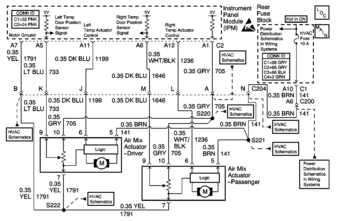
Circuit Description
The left temp door motor is an electronic actuator stepper motor with a feedback potentiometer. The IPM determines the position of the door motor based on the voltage from the potentiometer. Whenever the IPM battery power is interrupted (or by using the scan tool) the IPM will recheck motor travel range.
Conditions for Running the DTC
| • | The IPM power must be interrupted. |
| • | Perform the Recalibrate all Motors command using the scan tool. |
Conditions for Setting the DTC
The left temp door motors actual total travel range (max - min) is less than or greater than the calibrated limits.
Action Taken When the DTC Sets
| • | The IPM will continue to make use of whatever motor travel range is still available. |
| • | Each time the ignition switch is turned ON the IPM will recheck the motor travel range. |
Conditions for Clearing the DTC
The motor travel range error must be corrected.
Diagnostic Aids
| • | The range fault code can only be set following a check of the motor travel range. The motor travel range check can only be initiated by disrupting power to the IPM (disconnecting the battery) or with the scan tool. |
| • | The calibration limit is 152 to 220 counts (3.0-4.4 V). An actual range below this limit suggests an obstruction (something stuck in the door limiting travel). An actual range above this limit suggests an over travel condition (damaged or missing foam seals). |
| • | Refer to Testing for Intermittent Conditions and Poor Connections in Wiring Systems. |
Test Description
The number(s) below refer to the step number(s) on the diagnostic table.
Step | Action | Value(s) | Yes | No |
|---|---|---|---|---|
1 | Did you perform the HVAC Diagnostic System Check? | -- | Go to Step 2 | Go to Diagnostic System Check |
2 |
Does the scan tool display DTC B0234? | -- | Go to Step 3 | Go to Step 4 |
3 |
Does the result of the calculation indicate that the actual travel of the left temp door is within the specified range? | 152-220 Counts | Go to Step 12 | Go to Step 5 |
4 | With a scan tool, observe the current DTC list in the Instrument Panel Module. Does the scan tool display DTC B0237? | -- | Go to Diagnostic Aids | |
5 |
Does the voltage measure near the specified value? | B+ | Go to Step 6 | Go to Step 7 |
6 |
Did you find and correct the condition? | -- | Go to Step 16 | Go to Step 8 |
7 | Test the ignition positive voltage circuit of the left temp door motor for an open or a short to ground. Refer to Circuit Testing and Wiring Repairs in Wiring Systems. Did you find and correct the condition? | -- | Go to Step 16 | Go to Step 10 |
Does the drive shaft of the left temp door motor rotate and do the counts change? | -- | Go to Step 9 | Go to Step 13 | |
9 |
Does the voltage measure near the specified value when increasing temperature, near the specified value when decreasing temperature, and near the specified value when stationary? | 0 V increasing 5 V decreasing 2.5 V stationary | Go to Step 10 | Go to Step 12 |
10 |
Did you find and correct the condition? | -- | Go to Step 16 | Go to Step 11 |
11 | Replace the HVAC module. Refer to HVAC Module Assembly Replacement in Heating and Ventilation. Did you complete the replacement? | -- | Go to Step 16 | -- |
12 | Inspect for poor connections at the harness connector of the IPM . Refer to Testing for Intermittent Conditions and Poor Connections and Connector Repairs in Wiring Systems. Did you find and correct the condition? | -- | Go to Step 16 | Go to Step 14 |
13 | Inspect for poor connections at the harness connector of the left temp door motor. Refer to Testing for Intermittent Conditions and Poor Connections and Connector Repairs in Wiring Systems. Did you find and correct the condition? | -- | Go to Step 16 | Go to Step 15 |
14 | Replace the IPM. Refer to Instrument Panel Module Replacement in Body Control System. Did you complete the replacement? | -- | Go to Step 16 | -- |
15 | Replace the left temp door motor. Refer to Air Mix Actuator Replacement - Driver . Did you complete the replacement? | -- | Go to Step 16 | -- |
16 |
Does the DTC reset? | -- | Go to Step 2 | System OK |
