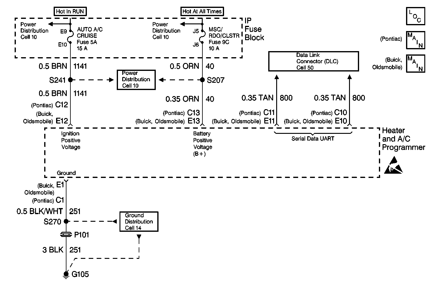
UART-based communication systems have a master of the serial data line
and remote transceivers. The master controls the message trafficon the serial
data line by polling the HVAC progrommer. The master then waits for the proper
response.
Code 036 is set.
Step
| Action
| Value(s)
| Yes
| No
|
1
|
- Turn the ignition switch to the RUN position.
- Connect a Scan Tool
.
- Attempt to establish communications on CKT 800.
Did the Scan Tool
establish communication?
| --
| Go to
Step 2
| Go to
Data Link Communications System Check
in Data Link Communications
|
2
|
- Verify that the Scan Tool
is still connected.
- Attempt to establish communications with the HVAC system (Non-E
and C).
Did the Scan Tool
establish communication?
| --
| Go to
Step 4
| Go to
Step 3
|
3
|
- Turn the ignition switch to the OFF position.
- Disconnect the HVAC programmer.
- Use the J-38125
.
- Disconnect the following terminals from the HVAC programmer harness
connector:
| • | For Oldsmobile and Buick, remove terminal E10 and terminal E11. |
| • | For Pontiac, remove terminal C10 and terminal C11. |
- Reconnect the HVAC programmer.
- Turn the ignition switch to the RUN position.
- Measure the voltage between DLC terminal 4 and the following
terminals:
Refer to
Measuring Voltage
in
Wiring Systems.
| 7.1. | For Oldsmobile and Buick, measure to the HVAC programmer terminal
cavity E10. |
| 7.2. | For Pontiac, measure to the HVAC programmer terminal cavity C10. |
- Measure the voltage between DLC terminal 4 and the following
terminals:
Refer to
Measuring Voltage
in
Wiring Systems.
| 8.1. | For Oldsmobile and Buick, measure to the HVAC programmer terminal
cavity E11. |
| 8.2. | For Pontiac, measure to the HVAC programmer terminal cavity C11. |
Does the voltage approximately equal the specified value at each cavity?
| 5 V
| Go to
Step 6
| Go to
Step 7
|
4
|
- Use the Scan Tool
.
- Turn the ignition switch to the OFF position.
- Turn the ignition switch to the RUN position.
Does DTC 038 reset?
| --
| Go to
Step 5
| System OK
|
5
| Replace
the HVAC programmer. Refer to
Programmer Replacement
.
Is the repair complete?
| --
| System OK
| --
|
6
|
- Inspect the following HVAC programmer harness connector terminals
for proper terminal contact:
Refer to
Intermittents and Poor Connections Diagnosis
in Wiring Systems.
| • | Terminal C7 and terminal C8 of the heater and A/C
programmer harness connector |
| • | For Oldsmobile and Buick, inspect terminals E10 and E11. |
| • | For Pontiac, inspect terminals C10 and C11. |
- Inspect CKT 800 for opens.
- If all of the terminals and CKT 800 are in proper condition,
replace the HVAC programmer. Refer to
Programmer Replacement
.
Is the repair complete?
| --
| System OK
| --
|
7
| Replace the HVAC programmer. Refer to
Programmer Replacement
.
Is the repair complete?
| --
| System OK
| --
|
