For 1990-2009 cars only
Ball Joint Inspection Front Suspension
Tools Required
J 8001 Dial Indicator
- Raise and support the vehicle with safety stands.
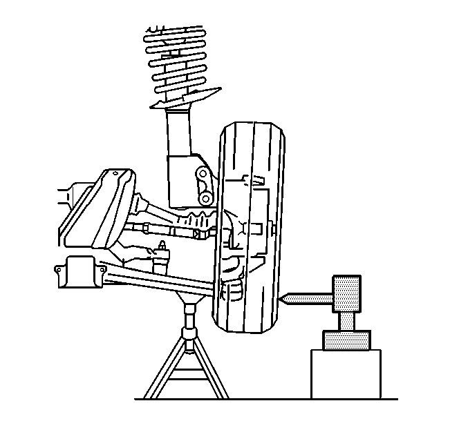
- Support the lower control arm with a jack stand, as far outboard as possible, near the lower ball joint.
- Wipe the ball joint clean. Check the seals for cuts or tears.
- Check the wheel bearings for looseness. Refer to Wheel Bearings Diagnosis .
- Check the ball joint for horizontal looseness.
- Check the lower ball joint for wear and for vertical looseness using the following procedure:
Important:
• The vehicle must rest on a level surface. • The vehicle must be stable. Do not rock the vehicle on the jack
stands.
Important: If a seal is cut or torn, replace the lower control arm.
| 5.1. | Position the J 8001 against the lowest outboard point on the wheel rim. |
| 5.2. | Rock the wheel in and out while reading the dial indicator. This shows horizontal looseness in the lower ball joint. |
| 5.3. | The dial indicator reading should be no more than 3.18 mm (0.125 in). If the reading is too high, check the lower ball joint for vertical looseness. |
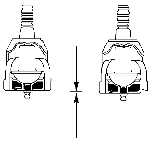
| 6.1. | Inspect by sight the lower ball joint for wear. The position of the housing into which the grease fitting is threaded indicates wear. This round housing projects 1.27 mm (0.050 in) beyond the surface of the lower ball joint cover on a new ball joint. Under normal wear, the surface of the lower ball joint housing retreats inward very slowly. |
| 6.2. | First observe, then scrape a scale, a screwdriver, or a fingernail across the cover. If the round housing is flush with or inside of the cover surface, replace the lower control arm. Refer to Lower Control Arm Replacement in Front Suspension. |
| 6.3. | Pry between the lower control arm and the steering knuckle while reading the dial indicator. This shows vertical looseness in the ball joint. The lower ball joint is not preloaded and may show some looseness. |
| 6.4. | If the dial indicator reading is more than 3.18 mm (0.125 in), replace the lower control arm. Refer to Lower Control Arm Replacement in Front Suspension. |
Ball Joint Inspection Rear Suspension-IRS
- Raise and suitably support the vehicle. Refer to Lifting and Jacking the Vehicle .
- Remove the rear tire and wheel assemblies. Refer to Tire and Wheel Removal and Installation .
- Perform a visual inspection of the ball joint seals for cuts or tears. If damage exists, replace the ball joint. Refer to Rear Axle Lower Control Arm Replacement .
- Check wheel bearing for looseness. Refer to Wheel Bearings Diagnosis .
- Remove the spring force from the lower control arm by supporting the lower control arm with a floor stand.
- Clamp the J 8001 Dial Indicator, to the bottom of the brake rotor. Place the dial indicator needle against the flange of the ball joint at the ball joint centerline most inboard point.
- Set the dial indicator to zero.
- Position a pry bar between the outer tie end-arm of the knuckle and the lower control arm. Lift the steering knuckle upward, then let it settle while observing the dial indicator. If the reading is 0.5 mm (0.020 in) or more, replace the ball joint. Refer to Rear Axle Lower Control Arm Replacement .
Position the floor stand as far outboard as possible and raise the control arm 75 mm (3 in).
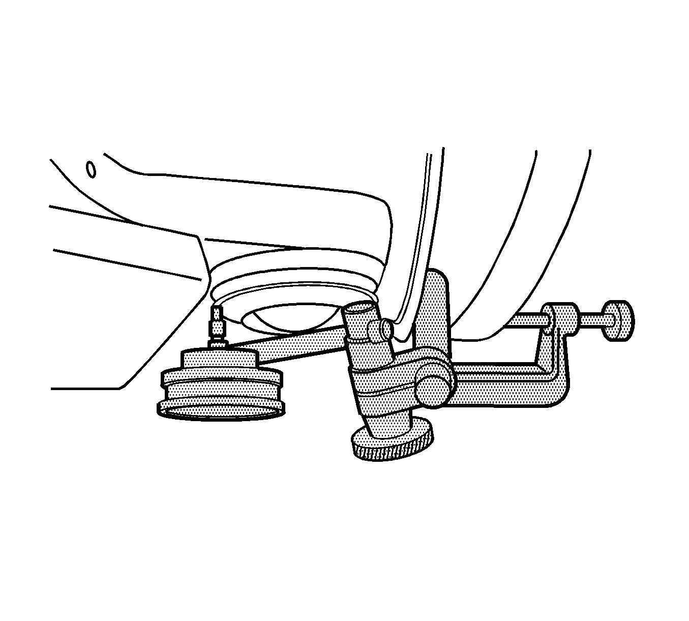
Important: If rotor does not have a hold down bolt, install 3 lug nuts to ensure the stability of the rotor.
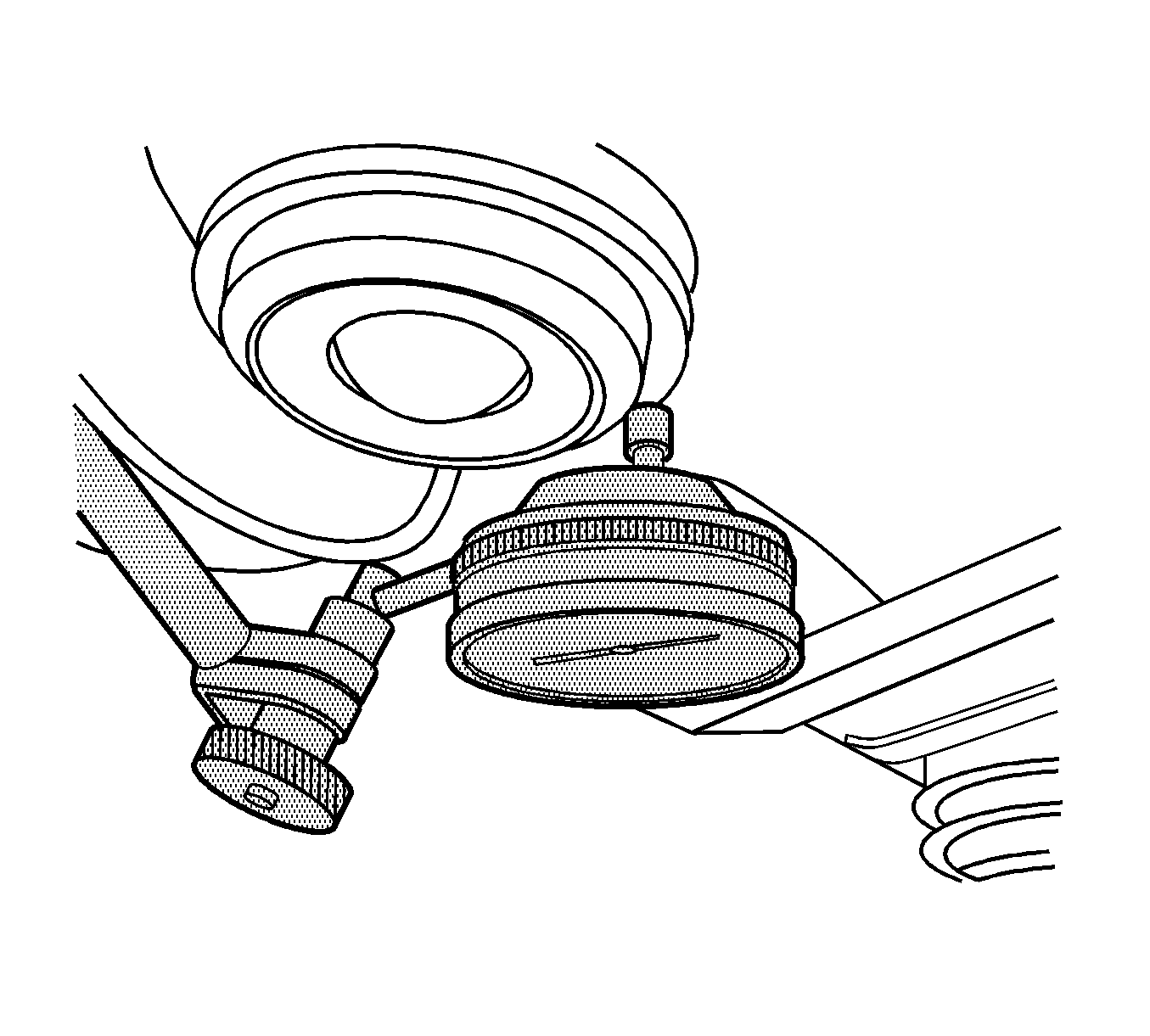
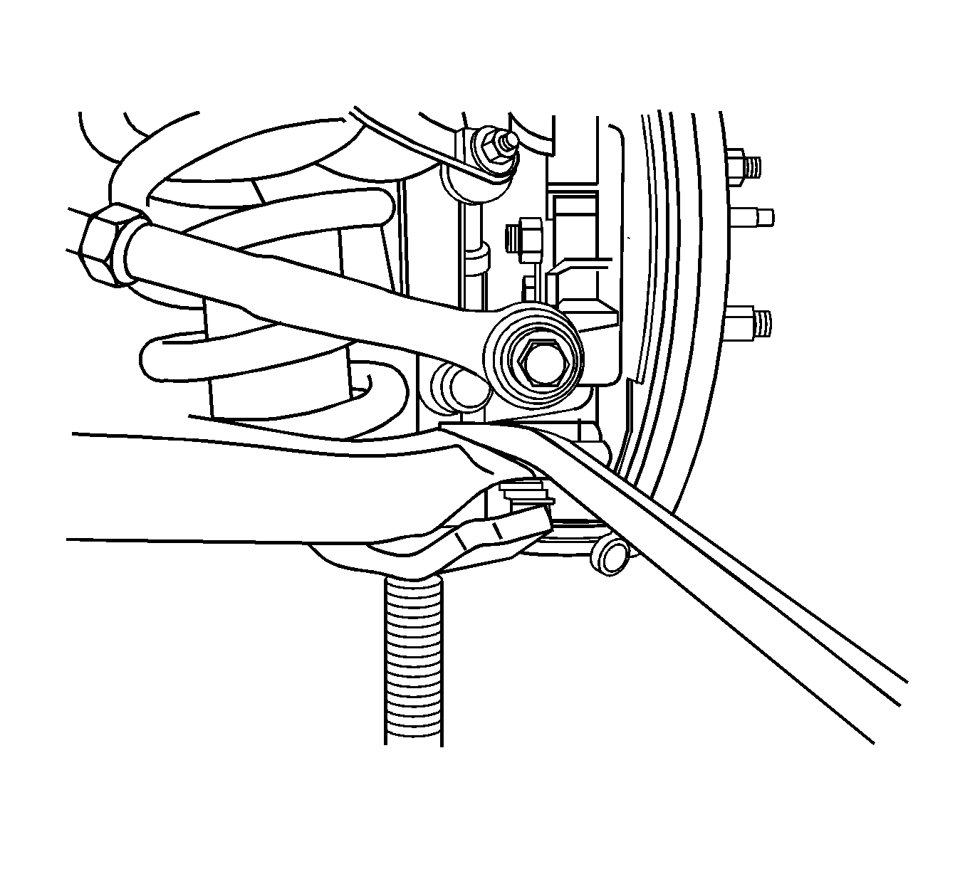
Important: Do NOT pry between the lower control arm and the wheel drive shaft boot or damage may result. Do NOT pry on the knuckle boss near the ball joint boot or damage to the ball joint may result.
