For 1990-2009 cars only
Removal Procedure
- Remove the knee bolster from the instrument panel (I/P). Refer to Knee Bolster Replacement .
- Disconnect the I/P wiring harness clip from the I/P support bracket.
- Disconnect the mode actuator electrical connector.
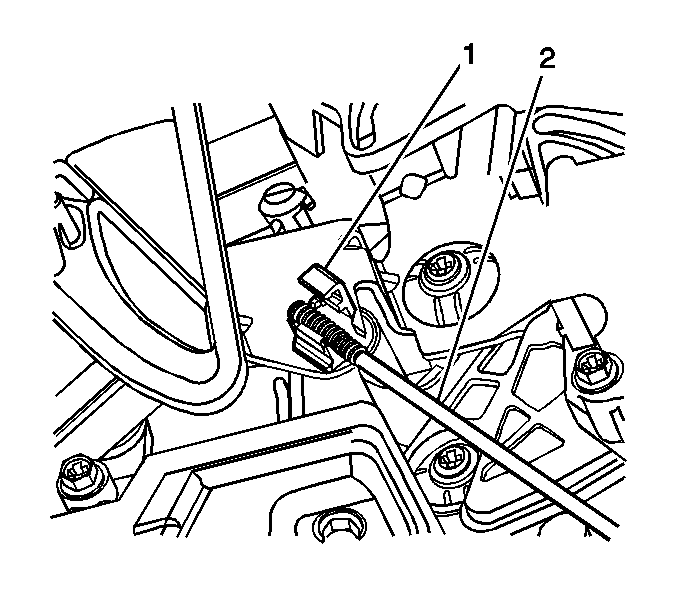
- Open the mode actuator push rod retainer clip (1) with a small flat-bladed screwdriver.
- Disconnect the mode actuator push rod (2) from the retainer clip (1).
- Remove the mode actuator mounting screws.
- Remove the mode door actuator.
Important: Disconnect the I/P wiring harness clip from the I/P support bracket to help access the mode actuator screws.
Important: Count the number of threads showing from the tip of the mode actuator push rod to the end of the retainer clip.
Installation Procedure
- Install the mode actuator.
- Install the mode actuator mounting screws.
- Connect the mode actuator push rod (2) to the retainer clip (1).
- Close the push rod retainer clip (1).
- Connect the mode actuator electrical connector.
- Connect the I/P wiring harness clip to the I/P support bracket.
- Install the knee bolster. Refer to Knee Bolster Replacement .
Notice: Refer to Fastener Notice in the Preface section.
Tighten
Tighten the screws to 1.6 N·m (14 lb in).
Important: Align the counted number of threads on the mode actuator push rod (2) with the tip of the retainer clip (1).
