Removal Procedure
- Remove the HVAC module assembly. Refer to HVAC Module Assembly Replacement .
- Remove the air inlet housing screws.
- Remove the air inlet housing from the HVAC module.
- Remove the right side HVAC module assembly mounting bracket screws.
- Remove the right side HVAC module assembly mounting bracket.
- Remove the HVAC module upper retaining screw.
- Remove the HVAC module assembly to dash panel sound barrier seal.
- Remove the screws retaining the heater outlet duct.
- Remove the heater outlet duct.
- Remove the heater core cover screws.
- Remove the heater core cover.
- Remove the heater core pipe retaining screw.
- Remove the heater core.
- Remove the lower HVAC module assembly retaining screw.
- Remove the lower HVAC module assembly retaining screws.
- Separate the upper and lower HVAC module halves.
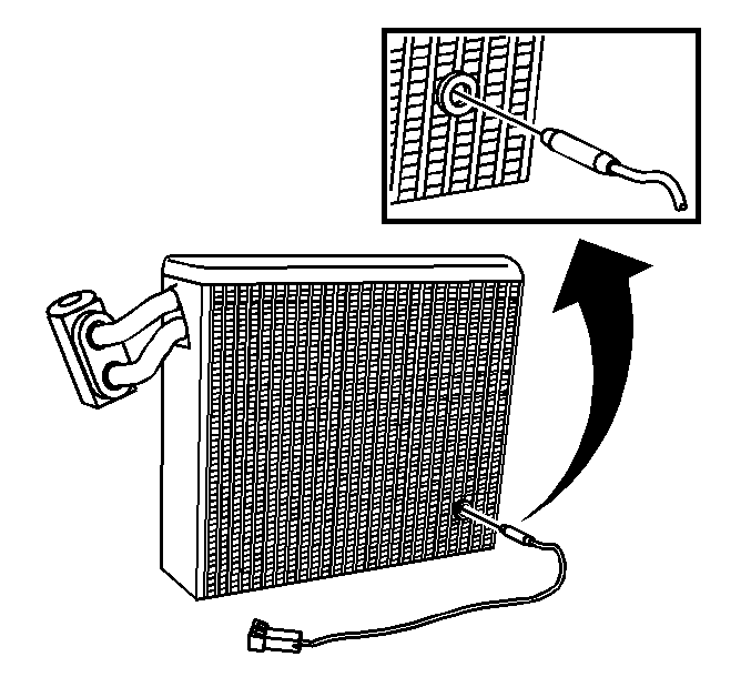
- Remove the evaporator core from the upper HVAC module case half.
- Remove the evaporator temperature sensor.
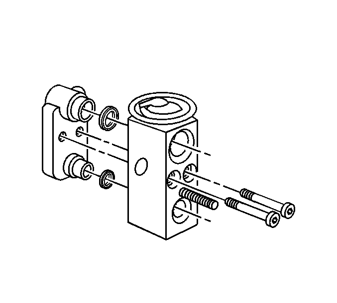
- Remove the thermal expansion valve (TXV) mounting screws.
- Remove the TXV from the evaporator core.
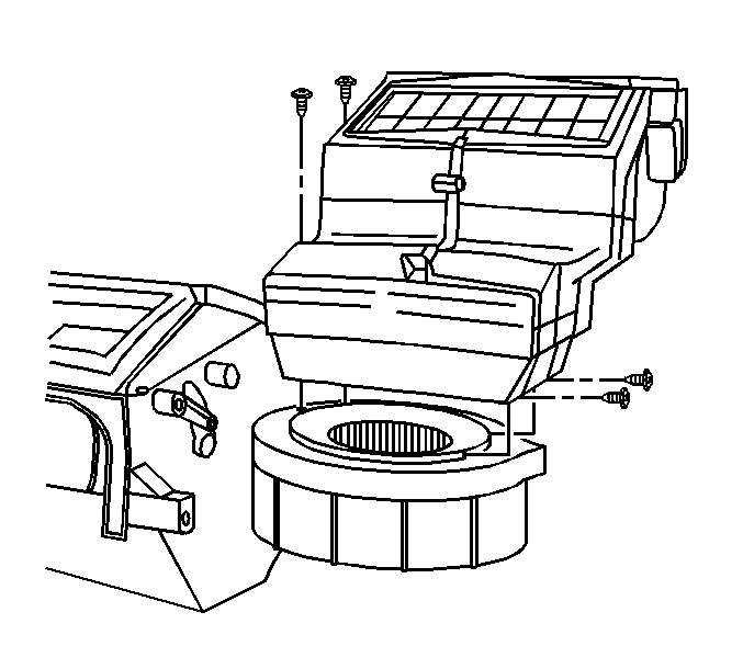
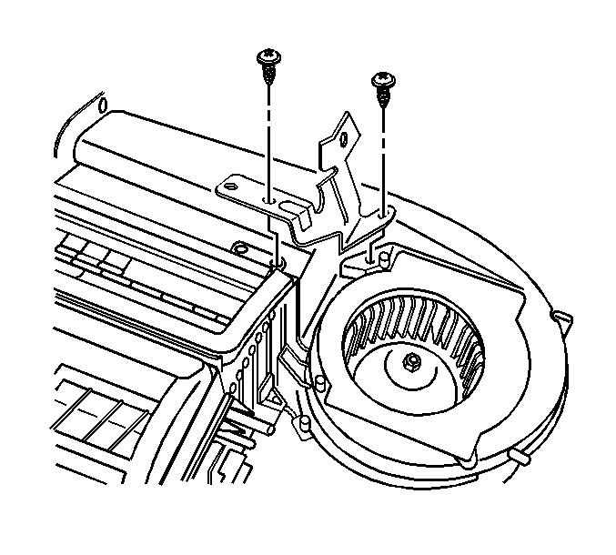
Important: The HVAC module assembly upper retaining screw is located under the right side HVAC module assembly mounting bracket.
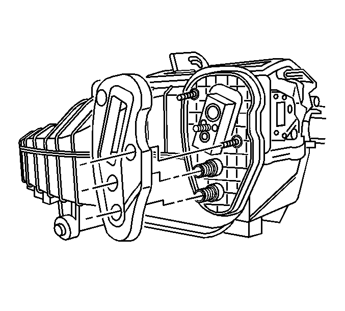
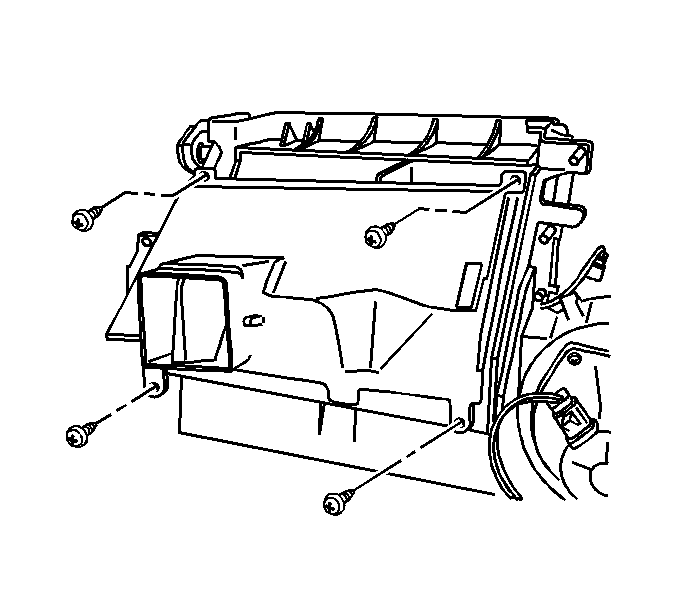
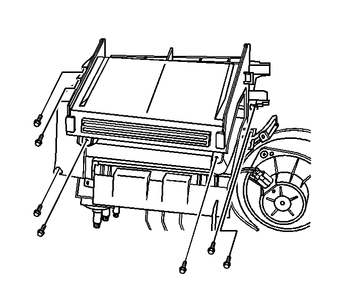
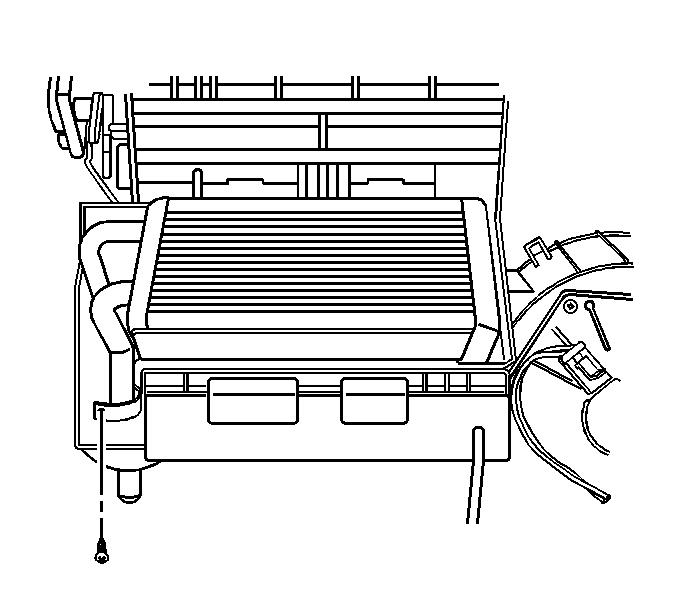
Important: The lower HVAC module assembly retaining screw is located under the heater core.
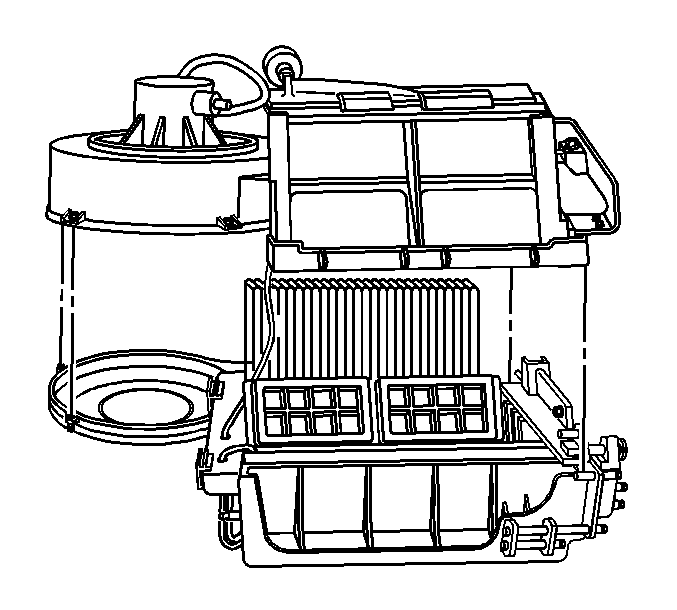
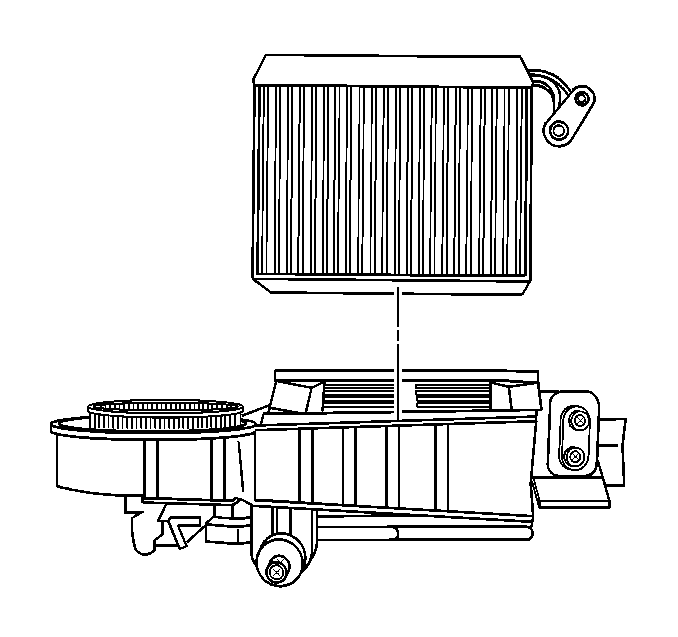
Installation Procedure
- If replacing the evaporator core, add the specified amount of PAG oil directly to the evaporator core. Refer to Refrigerant System Capacities .
- Install the new sealing washers onto the evaporator line. Refer to Sealing Washer Replacement .
- Install the TXV to the evaporator core.
- Install the TXV mounting screws.
- The evaporator temperature sensor should be approximately 3.5 cm (1.4 in) from the side and 5 cm (2 in) from the bottom corner of the evaporator core.
- Install the evaporator temperature sensor.
- Install the evaporator core into the upper HVAC module case half.
- Align and install the upper module case to the lower module case.
- Install the lower HVAC module assembly retaining screws.
- Install the lower HVAC module assembly retaining screw.
- Install the heater core.
- Install the heater core pipe retaining screw.
- Install the heater core cover.
- Install the heater core cover screws.
- Install the heater outlet duct.
- Install the heater outlet duct screws.
- Install the HVAC module assembly to dash panel sound barrier seal.
- Install the HVAC module upper retaining screw.
- Install the right side HVAC module assembly mounting bracket.
- Install the right side HVAC module assembly mounting bracket screws.
- Install the air inlet housing to the HVAC module.
- Install the air inlet retaining screws.
- Install the HVAC module assembly. Refer to HVAC Module Assembly Replacement .

Notice: Use the correct fastener in the correct location. Replacement fasteners must be the correct part number for that application. Fasteners requiring replacement or fasteners requiring the use of thread locking compound or sealant are identified in the service procedure. Do not use paints, lubricants, or corrosion inhibitors on fasteners or fastener joint surfaces unless specified. These coatings affect fastener torque and joint clamping force and may damage the fastener. Use the correct tightening sequence and specifications when installing fasteners in order to avoid damage to parts and systems.
Tighten
Tighten the screws to 3.2 N·m (28 lb in).

Important: The evaporator temperature sensor must be located in the same position on the new evaporator core.

Important: Align the evaporator temperature sensor wires with the opening in the upper HVAC module case. Improper alignment will pinch and/or cut the sensor wires.

Tighten
Tighten the screws to 0.9 N·m (8 lb in).
Tighten
Tighten the screw to 0.9 N·m (8 lb in).

Tighten
Tighten the screw to 0.9 N·m (8 lb in).

Tighten
Tighten the screws to 0.9 N·m (8 lb in).

Tighten
Tighten the screws to 0.9 N·m (8 lb in).


Tighten
Tighten the screw to 0.9 N·m (8 lb in).
Tighten
Tighten the screws to 1.8 N·m (16 lb in).

Tighten
Tighten the screws to 0.9 N·m (8 lb in).
