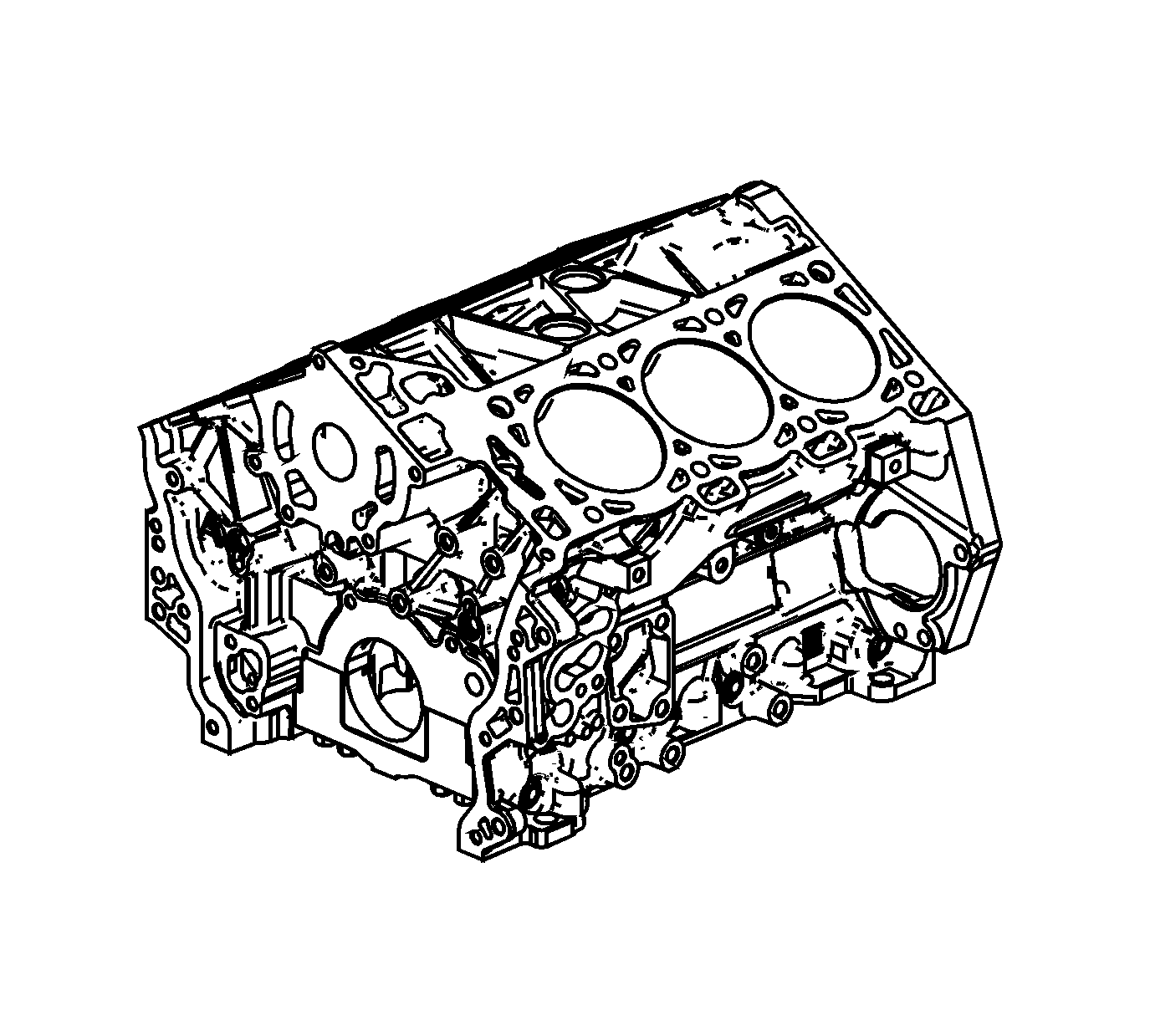
Special Tools
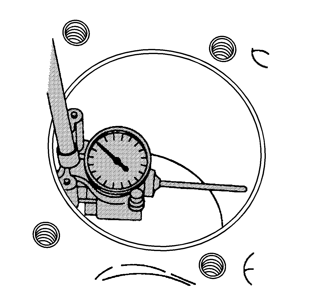
| • | EN 8087 Cylinder Bore Gage
|
| • | EN 49485 Gasket Remover
|
For equivalent regional tools, refer to
Special Tools.
Cleaning Procedure
- Remove any old thread sealant, gasket material or sealant using
EN 49485 remover
.
- Clean all the following areas with solvent:
- Clean all threaded and through holes with solvent.
Warning: Wear safety glasses when using compressed air, as flying dirt particles may cause eye injury.
- Dry the engine block with compressed air.
Visual Inspection

- Inspect the crankshaft bearings journals for damage or spun bearings. The crankshaft bearing journals are
not repairable, if the crankshaft bearing journals are damaged the cylinder block assembly must be replaced.
- Inspect the primary camshaft drive chain tensioner mounting surface on the engine block for burrs or any defects that would degrade the sealing of the NEW primary camshaft drive chain tensioner gasket.
- Inspect all sealing and mating surfaces for damage, repair or replace the cylinder block assembly if necessary.
- Inspect all threaded and through holes for damage or excessive debris.
- Inspect all bolts for damage, if damaged replace with NEW bolts only.
- Inspect the cylinder walls for cracks or damage. The cylinder sleeves are not serviced separately, if the cylinders are damaged the cylinder block assembly must be replaced.
- Inspect the engine block for cracks. Do not repair any cracks. If cracks are found, the cylinder block assembly must be replaced.
- Repair any damaged threaded holes. Refer to
Thread Repair Specifications.
Measuring Cylinder Bore Diameter

Measure the cylinder bore diameter 37 mm (1.457 in) from the deck face using the
EN 8087 gage
.
Compare your results with the
Engine Mechanical Specifications. If the cylinder diameter exceeds the specifications, the cylinder block may be oversized to 0.25 mm (0.010 in). There is only one size
of oversized pistons and rings available for service.
Measuring Cylinder Bore Taper
- Measure the cylinder bore along the thrust surfaces, perpendicular to the crankshaft centerline, at 10 mm (0.397 in) below the deck surface and record your measurement.
- Measure the cylinder bore along the thrust surfaces, perpendicular to the crankshaft centerline, at 100 mm (3.976 in) below the deck surface and record your measurement.
- Calculate the difference between the 2 measurements. The result will be the cylinder taper.
- Compare your results with the
Engine Mechanical Specifications. If the cylinders exceed the specifications, the cylinder block may be oversized to 0.25 mm (0.010 in). There is only one size
of oversized pistons and rings available for service.
Measuring Cylinder Bore Out-of-Round
- Measure both the thrust and non-thrust cylinder diameter at 10 mm (0.397 in) below the deck. Record your measurements.
- Calculate the difference between the 2 measurements. The result will indicate out-of-round at the upper end of the cylinder.
- Measure both the thrust and non-thrust cylinder diameter at 100 mm (3.976 in) below the deck surface. Record your measurements.
- Calculate the difference between the 2 measurements. The result will indicate out-of-round at the lower end of the cylinder.
- Compare your results with the
Engine Mechanical Specifications. If the cylinders exceed these specifications, the cylinder block may be oversized to 0.25 mm (0.010 in). There is only one size
of oversized pistons and rings available for service.
Deck Flatness Inspection

- Ensure the engine block decks are clean and free of gasket material.
- Inspect the surface for any imperfections or scratches that could inhibit proper cylinder head gasket sealing.
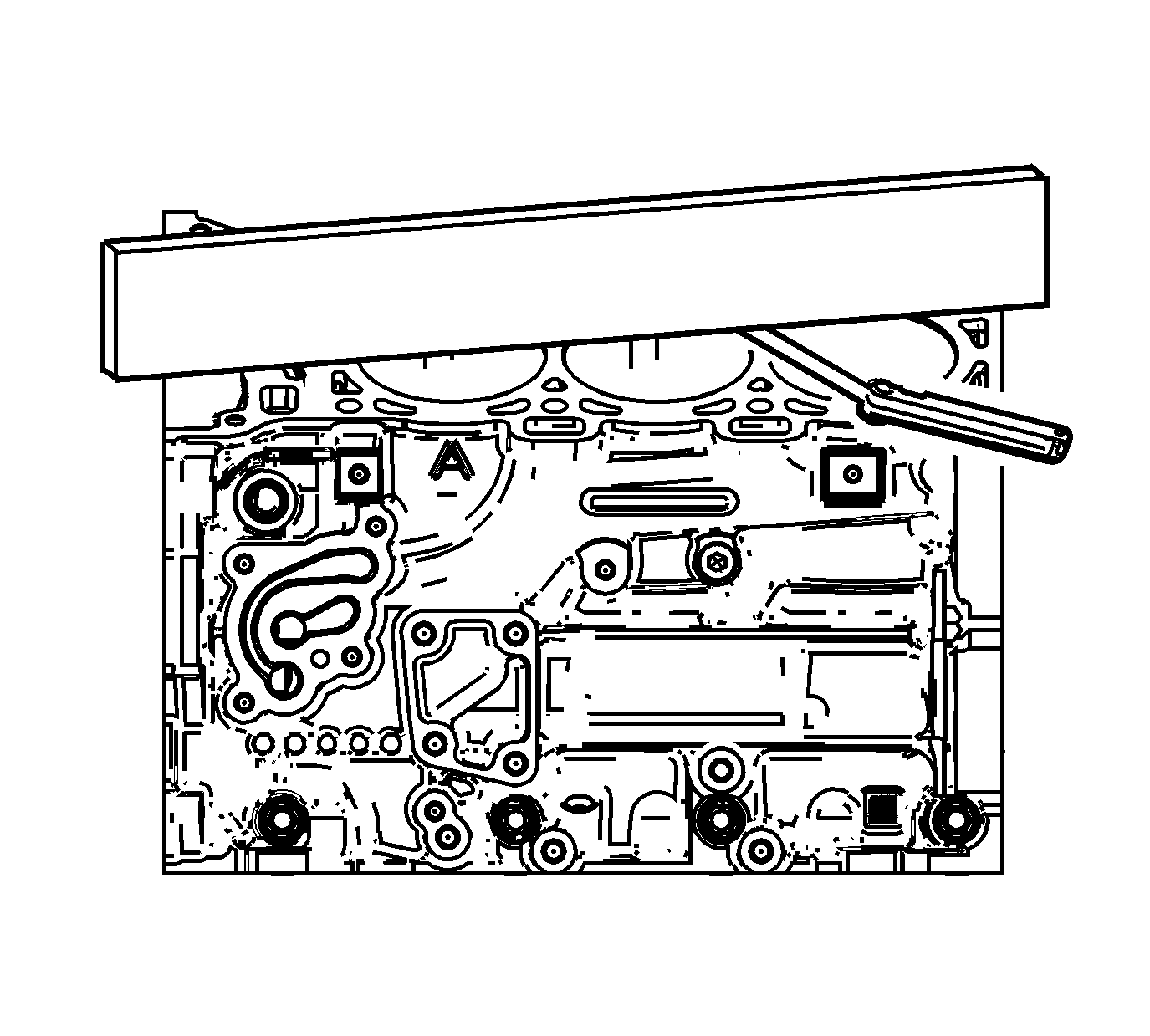
- Place a straight-edge diagonally across the cylinder block deck face surface.
- Measure the clearance between the straight-edge and the cylinder block deck face using a feeler gage at 4 points along the straight-edge.
- If the warpage is less than 0.05 mm (0.002 in), the cylinder block deck surface does not require resurfacing.
- If the warpage is between 0.05-0.20 mm (0.002-0.008 in) or any imperfections or scratches that could inhibit proper cylinder head gasket sealing are present, the cylinder block deck surface requires resurfacing.
- If resurfacing is required the maximum amount that can be removed is 0.25 mm (0.010 in).
- If the cylinder block deck surface requires more than 0.25 mm (0.010 in) material removal the block must be replaced.


