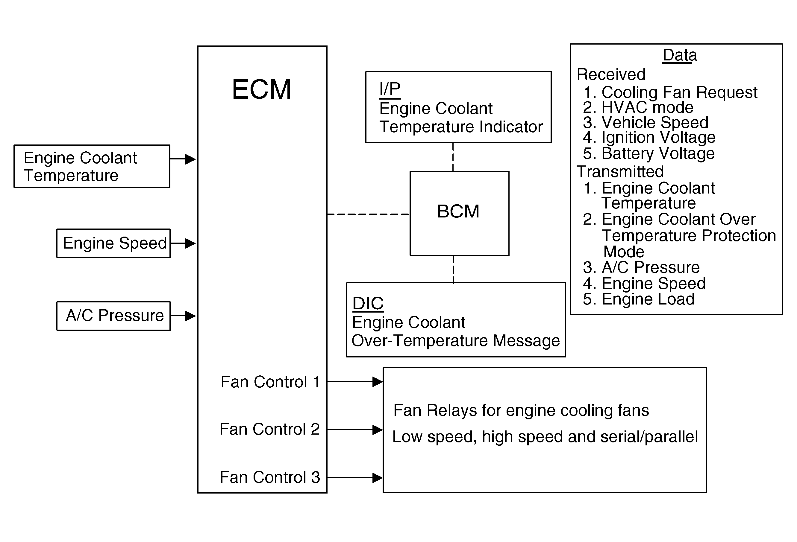
Cooling Fan Description and Operation V6
The engine control module (ECM) commands the fans ON in either high speed, medium speed, or low speed, depending on cooling requirements.
Low Speed
In low speed operation, the ECM applies ground to the coil side of the following relays with the cooling fan relay 1 control circuit:
| • | Cooling Fan Left Low Speed Relay |
| • | Cooling Fan Right Low Speed Relay |
| • | Cooling Fan Speed Control Relay |
This energizes the relay coils. The low speed cooling fan relays supply power to the appropriate cooling fan motor through an internal fan resistor. The fan speed control relay contacts close and supply a direct ground path for the left cooling fan motor. The right cooling fan motor is connected to a dedicated ground. This results in both fans operating at low speed.
Medium Speed
In medium speed operation, the ECM commands the low speed fan relays, and the speed control relay off. The ECM simultaneously commands both of the cooling fan high speed relays on with the cooling fan relay 2 control circuit. The cooling fan motors are supplied power directly from the cooling fan high speed relays. The right cooling fan is connected to a dedicated ground, and operates at high speed. The left cooling fan is supplied a ground through the right cooling fan resistor and fan motor, which is connected to the de-energized cooling fan speed control relay. This results in the right cooling fan operating at a reduced speed.
High Speed
In high speed operation, the ECM applies a ground to the coil side of all five cooling fan relays. When energized, the high speed relays apply voltage directly to the cooling fans through the switch side of the relays. The energized cooling fan speed control relay provides a direct ground circuit for the left cooling fan. This arrangement allows each fan to receive full voltage and operate at high speed.
Cooling Fan Description and Operation LDK Single Fan
The engine cooling fan system is composed of one fan, 5 relays, the engine control module (ECM), and the associated wiring. The fan assembly includes two resistors, which enable the fan to operate at 3 speeds.
In low speed operation, the ECM provides ground to ECM terminal X2 46. The Cooling Fan Relay activates and provides ground to the coils of the Cooling Fan Medium Speed 2 Relay and the Cooling Fan Speed Control Relay. The Cooling Fan Speed Control Relay activates and provides power to the coil of the Cooling Fan High Speed Relay. The Cooling Fan High Speed Relay remains inactive because ECM terminal X2 45 is not grounded. The Cooling Fan Medium Speed 2 Relay provides power to the cooling fan motor through cooling fan terminal 2 and the internal fan resister.
In medium speed operation, the ECM provides ground to ECM terminal X2 45. The Cooling Fan High Speed Relay remains inactive because power is not provided to the coil from the Cooling Fan Speed Control Relay. The Cooling Fan Medium Speed 1 Relay activates and provides power to the cooling fan motor through cooling fan terminal 3 and the internal fan resistor.
In high speed operation, the ECM provides ground to ECM terminals X2 45 and X2 46. As previously described, power is now provided to both cooling fan terminals 2 and 3. In addition, power and ground are now provided to the coil of the Cooling Fan High Speed Relay. The Cooling Fan High Speed Relay activates and provides power to the cooling fan motor through cooling fan terminal 4.
Cooling Fan Description and Operation Diesel

The engine cooling fan system consists of 2 electrical cooling fans and 5 fan relays, 2 in UEC and 3 in the relay box, providing 4 different speed levels. The relays are arranged in a series parallel (S/P) configuration that allows the engine control module (ECM) to operate both fans together at low or high speeds, depending on cooling requirements. The cooling fans and fan relays receive battery positive voltage from the underhood fuse block. The ground path is provided at G104.
The engagement of the different steps is depending either on coolant temperature or A/C pressure. If the coolant temperature is too high at ignition off there will be an afterrun for maximum 2 minutes.
At step 1 (lowest speed) ECM activates relay K9 in UEC and the fan motors are in serial circuit. One motor is without pre-resistor, the other one with pre-resistor.
At step 2 ECM activates the relays in the relay box and both fan motors are connected in parallel, both with pre-resistors.
At step 3 ECM activates relay K9 in UEC and the relays in the relay box and the motors are in serial circuit, one with and one without pre-resistor.
At step 4 ECM activates K9 and K13 in UEC as well as the relays in the relay box and the motors will be in parallel with no pre-resistor.
Refer to Engine Cooling Schematics.
