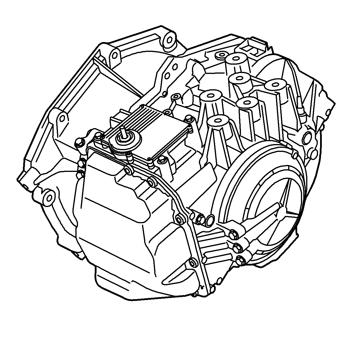
The AF 40-6 automatic transmission is an electronic 6-speed automatic gearbox with lock-up. The gearbox is mounted directly against the engine and has a final drive with integrated differential. The power unit is transverse mounted with front-wheel drive. Gear positions P-R-N-D are selected with the selector lever mounted in the centre console. Manual up/downshifting is possible.
Gearbox functions can be divided into three parts:
| • | Mechanical |
| • | Hydraulic |
| • | Control system |
Mechanical
| • | Torque converter with lock-up clutch |
| • | 2 planetary gear units, of which the rear is double. |
| • | 3 disc clutches |
| • | 1 band type brake |
| • | 1 multi-disc brake |
| • | 1 free wheel |
| • | Final drive with differential |
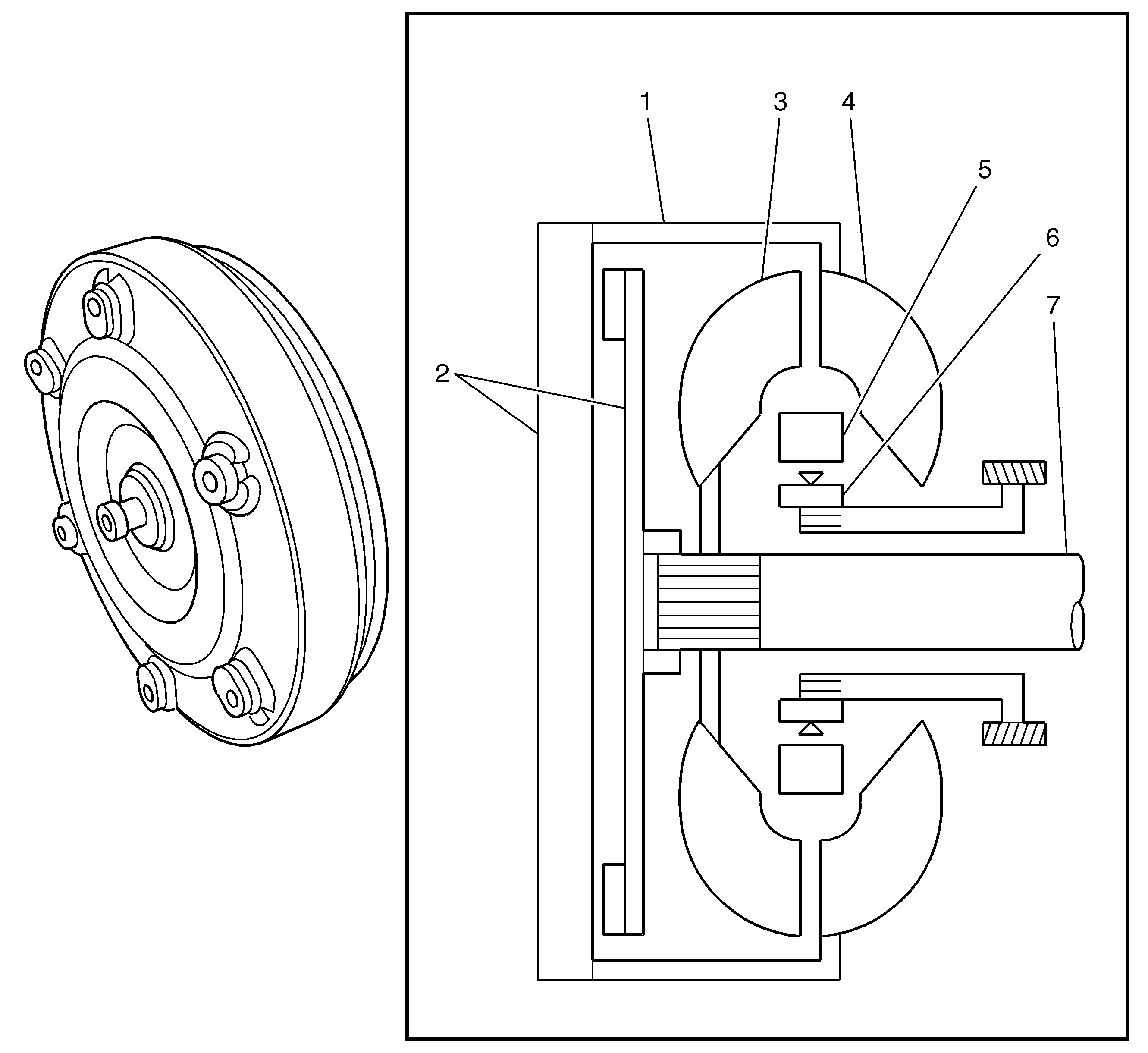
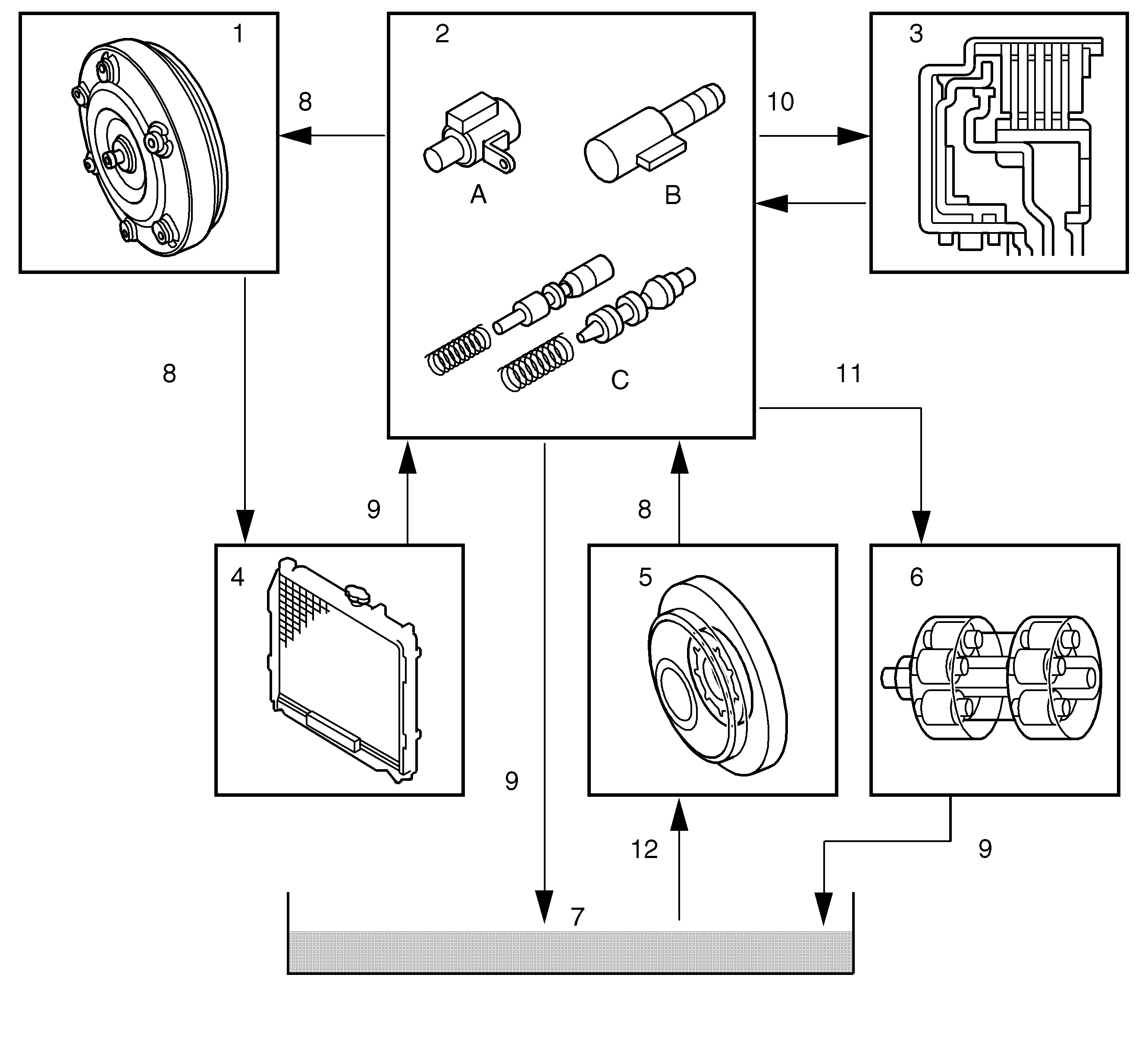
Component | Function | |
1 | Torque converter housing | |
2 | Torque converter clutch | Disc clutch, also called lock up. Locks the impeller to the turbine using oil pressure. |
3 | Turbine | Coupled to gearbox input shaft, drives the car when lock up is not active. |
4 | Impeller | Driven by engine, throws oil against the turbine. |
5 | Stator | Redirects the oil towards the impeller once it has left the turbine. Responsible for torque amplification |
6 | Free wheel | The stator is mounted on the free wheel. This means the stator can rotate when the turbine has built up speed and so reduces energy loss. |
7 | Input shaft |
The torque converter is bolted to the engine flywheel (flexplate). The converter is filled with oil via pressure from the automatic transmission pump. This is itself a hydraulic gearbox that amplifies the engine torque the more it slips. The greatest torque amplification is obtained when the engine stalls (car stationary and full throttle in Drive), as the engine torque is at a maximum while the gearbox input shaft is stationary. There will not be any amplification if the engine speed is the same as the gearbox input shaft speed.
The torque converter clutch (lock up) is activated at a steady speed when there is no need for torque amplification. The difference in speed between the engine and the gearbox does give an amplification of torque even at steady speeds but also entails heat loss. These losses result in unnecessary fuel consumption.
Note: The car must not be stalled (car held with brakes and full throttle in D position) for longer than 5 seconds.
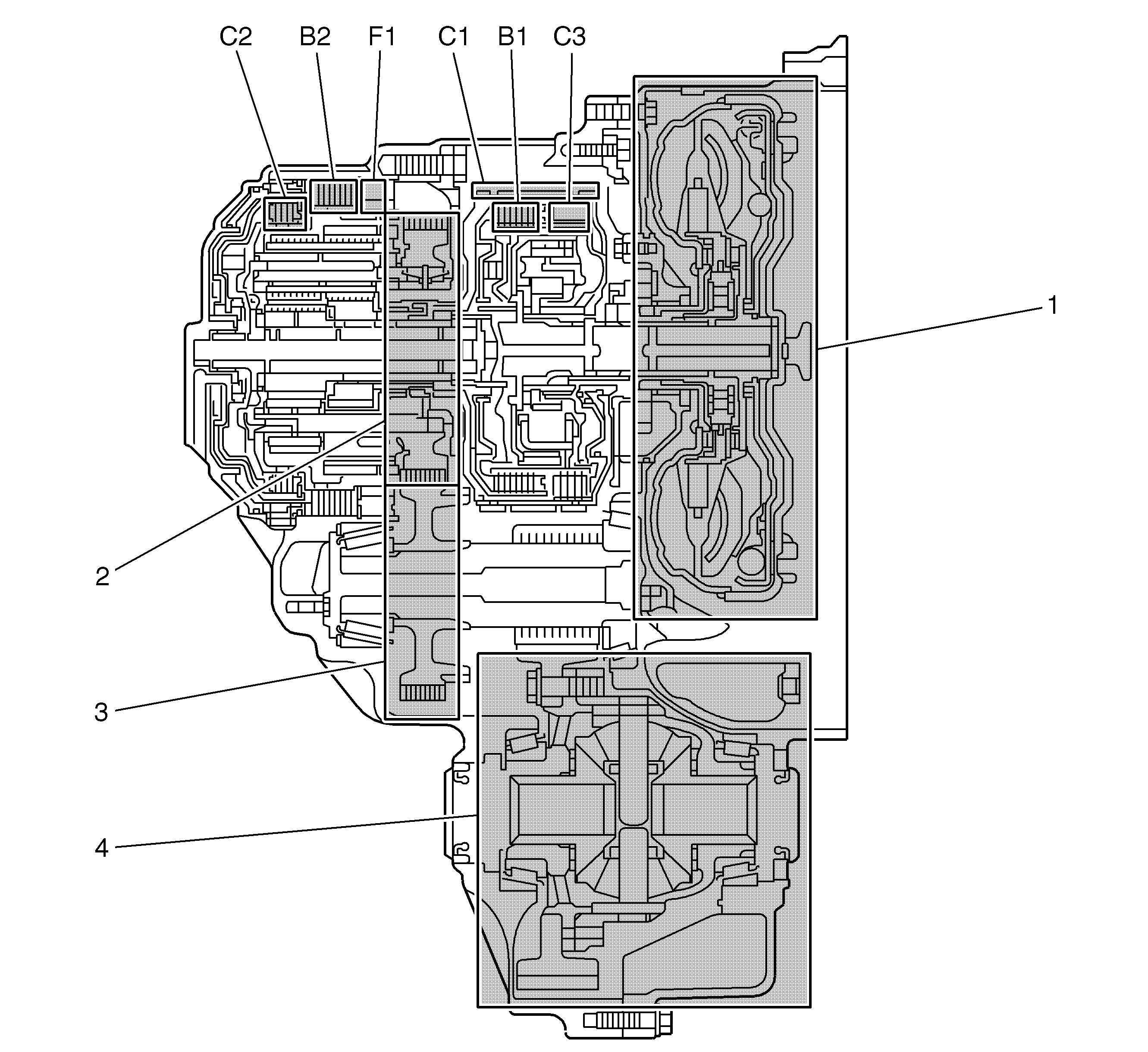
- Torque converter
- Gearbox's output gear
- Intermediate shaft
- Differential
The gearbox has 2 planetary gear units; front and rear. The front one is a single planetary gear and the rear one is double. The rear unit is Ravigneaux type with two planet gears between the rear sun gear and the only ring gear, which is the gearbox output shaft. The two planet gears are fitted on a common planet carrier.
The front planetary gear sun gear is fixed and the power from the torque converter enters via its ring gear. This entails a reduction of the planet carrier speed used for gear 1-5 and R. The power from the planet carrier is conveyed to the rear planetary gear unit via clutches C1 and C3.
The rear planetary gear unit receives power either directly from the torque converter via clutch C2 or from the front planetary gear via clutches C1 and C3. The 2 brakes, B1 and B2, are used to hold firm the components in the rear planetary gear unit. B2 is combined with a free wheel (F1).
The activation of one or more friction elements results in a gear ratio. Brakes and clutches are activated hydraulically using solenoids controlled by the transmission control module (TCM).
The table shows the active elements for each of the gears.
C1 | C2 | C3 | B1 | B2 | B3 | |
P/N | ||||||
R | X | X | ||||
1 | X | (X) | X | |||
2 | X | X | ||||
3 | X | X | ||||
4 | X | X | ||||
5 | X | X | ||||
6 | X | X |
(X) Only when engine braking
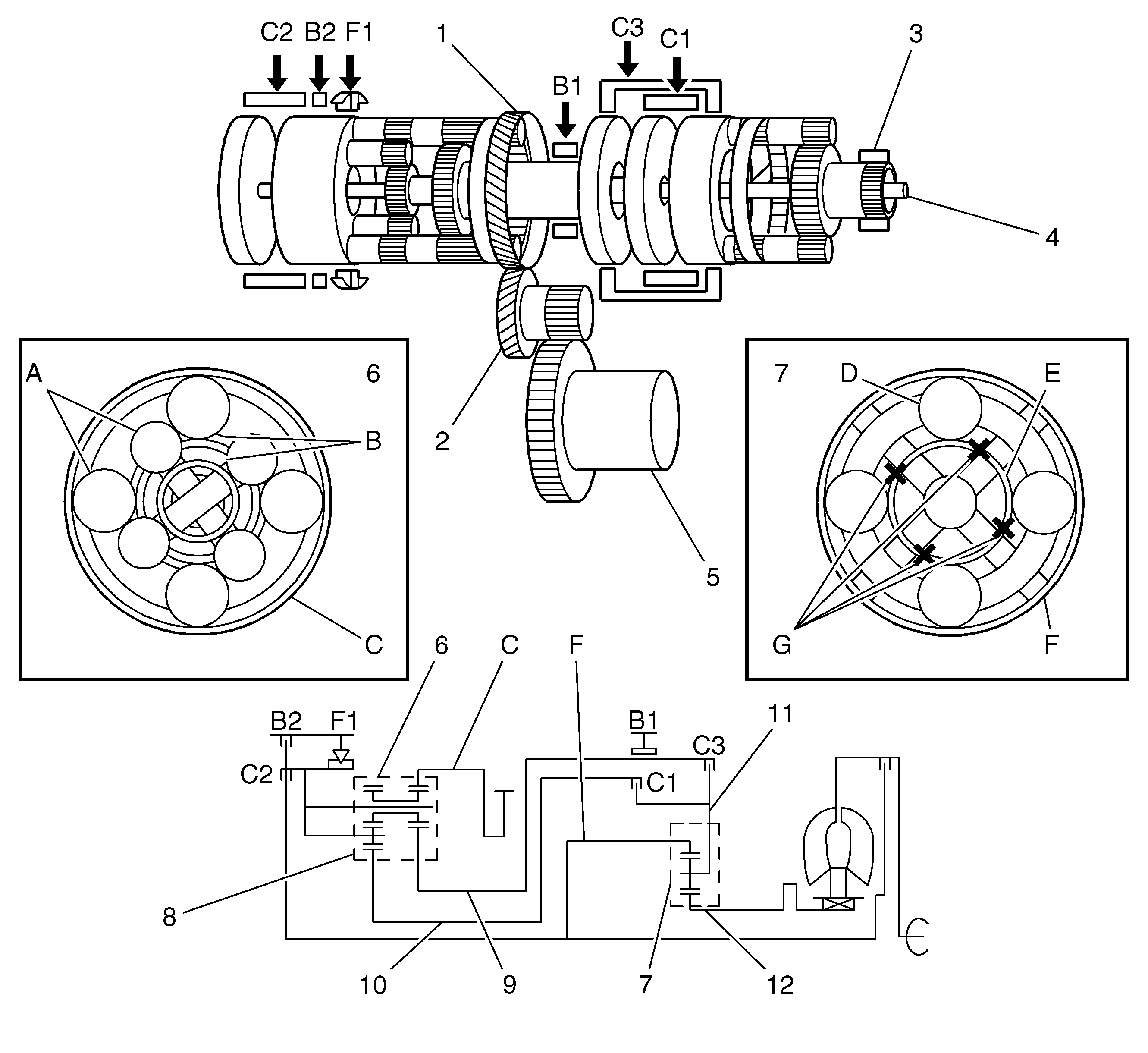
- Output shaft gear
- Intermediate shaft
- Location of oil pump
- Input shaft
- Differential gear
- Rear planetary gear unit:
- Front planetary gear:
- Planet carrier
- Front sun gear in rear planetary gear unit
- Rear sun gear
- Front planet carrier
- Front sun gear
| • | A) planet gear, |
| • | B) sun gear, |
| • | C) ring gear |
| • | D) planet gear, |
| • | E) sun gear, |
| • | F) ring gear, |
| • | G) lock |
Gear | Front planetary gear | Rear planetary gear unit |
R | The planet carrier rotates clockwise at reduced speed. | The front sun gear rotates clockwise (C3). The planet carrier is braked (B2). The ring gear rotates anticlockwise with reverse gear ratio. |
1 | The planet carrier rotates clockwise at reduced speed. | The rear sun gear rotates clockwise (C1). The planet carrier is braked by the free wheel (and by B2 when engine braking). The ring gear rotates clockwise with 1st gear ratio. |
2 | The planet carrier rotates clockwise at reduced speed | The rear sun gear rotates clockwise (C1). The front sun gear is braked (B1). The ring gear rotates clockwise with 2nd gear ratio. |
3 | The planet carrier rotates clockwise at reduced speed. | The rear and front sun gears rotate clockwise (C1 and C3). The planetary gear unit is locked and rotates as one unit. The ring gear rotates clockwise with 3rd gear ratio. |
4 | The planet carrier rotates clockwise at reduced speed. | The rear sun gear and planet carrier rotate clockwise (C1 and C2). The ring gear rotates clockwise with 4th gear ratio. |
5 | The planet carrier rotates clockwise at reduced speed. | The front sun gear rotates clockwise (C3). The planet carrier rotates clockwise (C2). The ring gear rotates clockwise with 5th gear ratio. |
6 | Not used | The planet carrier rotates clockwise (C2). The front sun gear is braked (B1). The ring gear rotates clockwise with 6th gear ratio. |
Gear changing performance is controlled by the applied element. When changing gear, it is not possible to apply more than one friction element for consistent behavior. In the same way, it is not possible to release more than one friction element when changing gear. This means it is not possible to change from one gear to an optional gear. The following shows the normal gear changing sequence from standstill:
N to D (1) | Apply C1 |
1 to 2 | Apply B1 |
2 to 3 | Release B1, apply C3 |
3 to 4 | Release C3, apply C2 |
4 to 5 | Release C1, apply C3 |
5 to 6 | Release C3, apply B1 |
In this sequence you can clearly see that no more than 1 element is released or applied at one time. If you suddenly release the accelerator in 3rd gear after accelerating at full throttle, it is logical to change up to 6th gear.
Changing directly from 3 to 6, however, is not suitable because C1 and C3 must then be released and C2 and B1 applied. Changing 3 to 5 and 5 to 6 must be done instead. The need of these intermediate changes is especially noticeable during kickdown at various speeds. The permitted changing sequences are determined by a program in TCM.
The transmission is blocked mechanically in selector lever position P.
Hydraulic
- Torque converter
- Valve housing:
- Clutch, brake
- Oil cooler
- Oil pump
- Planetary gear
- Oil pressure
- Gearbox oil, inlet
- Gearbox oil, return
- Operating pressure
- Lubrication
- Oil flow to pump
| • | A) solenoid, |
| • | B) linear solenoid, |
| • | C) control valve |
A special automatic transmission fluid must be used. The gearbox does not have an oil dipstick. The drain plug has an extra, central plug for checking the level that is connected to a pipe that reaches up to the correct level in the box. Fill the oil through the conventional filler plug until the level is correct and oil runs out of the level hole.
The temperature of the oil is important when checking the level. The temperature can be read with a scan tool.
All the friction elements are applied hydraulically. The hydraulic pressure is generated by a pump driven by the engine. The pump is mounted in the gearbox behind the torque converter. The drive is direct from the torque converter.
Oil passes to the valve housing where the manual valve is integrated. The valve is affected by the gear selector wire, which in turn is operated by the selector lever. The valve has 3 positions, P/N, R and D/M. In position P/N, the oil will drain directly back to the gearbox sump. In position R, the oil will pass directly to brake B2, which is used for reverse gear. In position D/M, oil will pass to the circuits used for the forward gears.
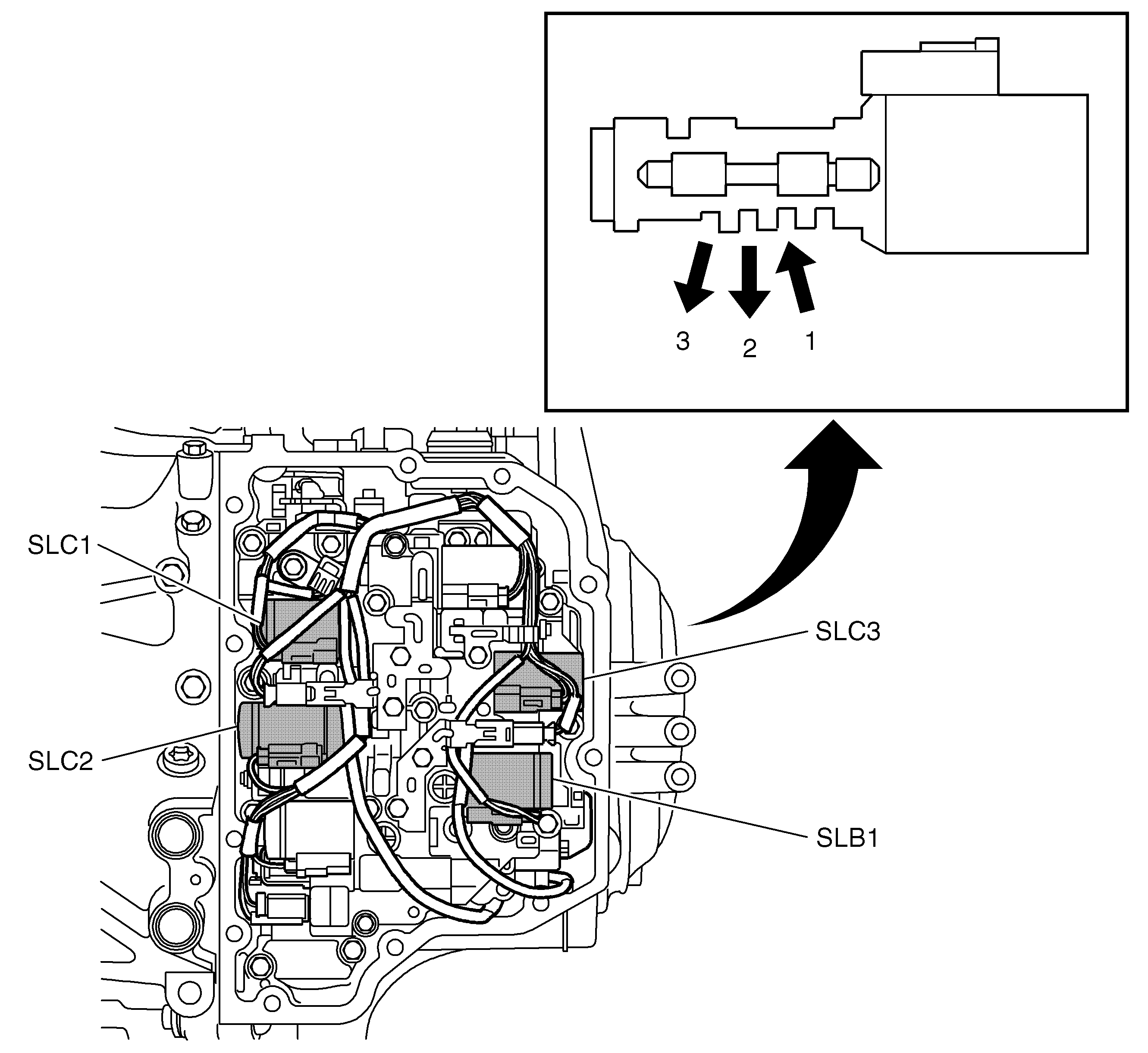
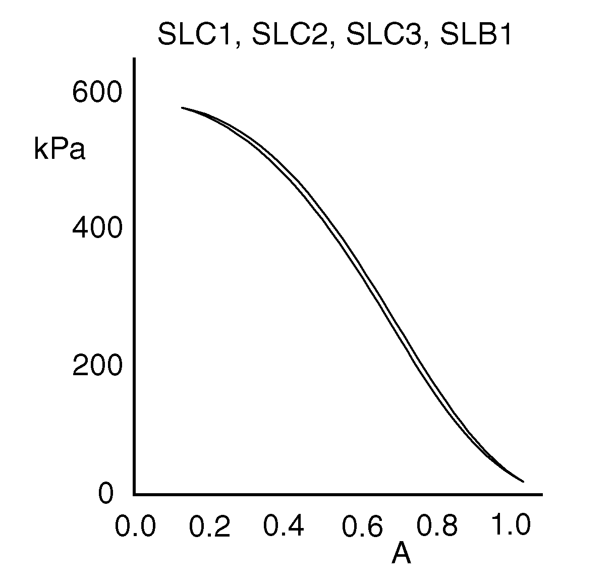
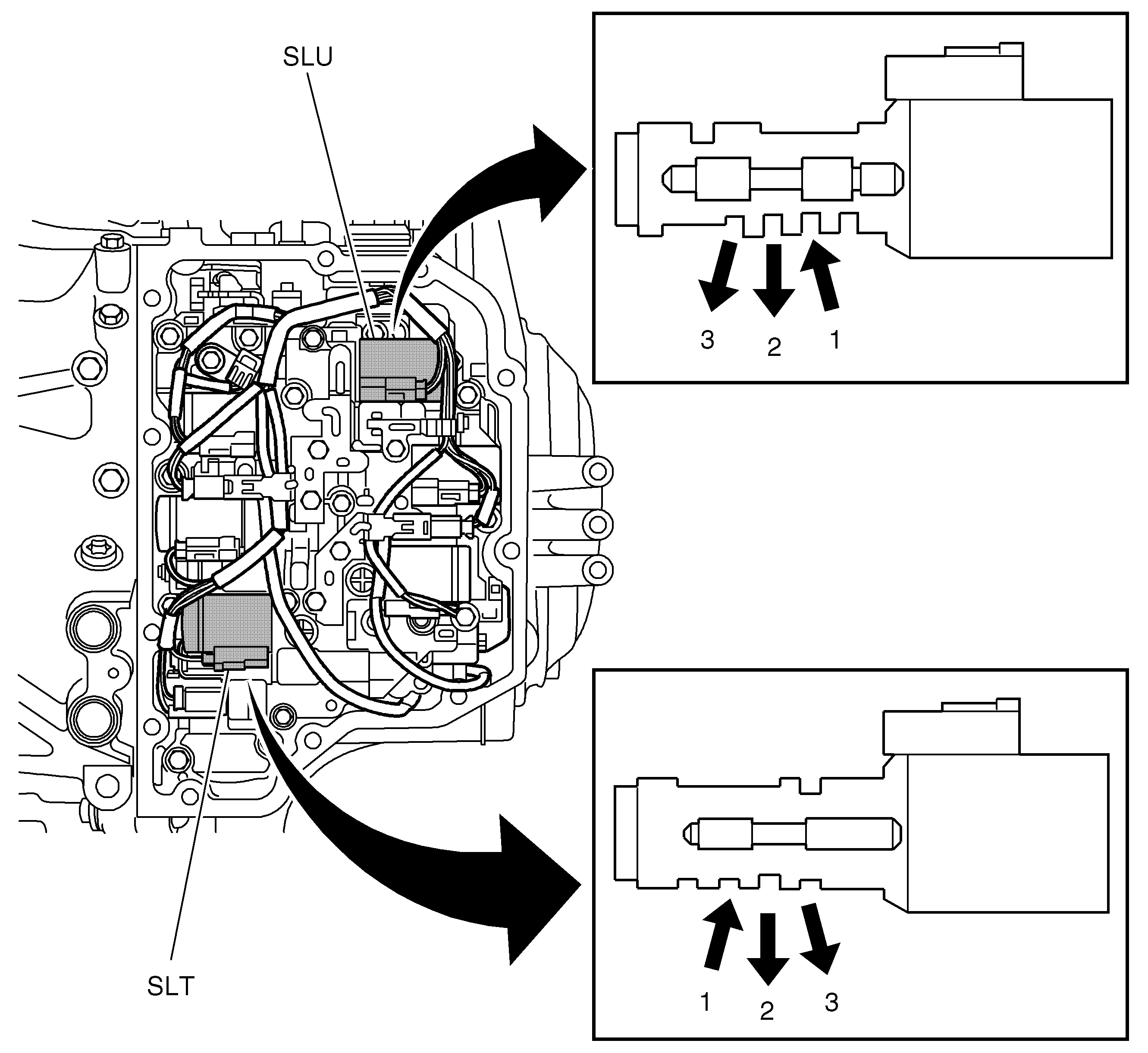
To control the flow of oil to and from the friction elements, 6 stepless (linear) solenoids are used. With them, TCM can regulate the pressure precisely. Each solenoid is connected to a mechanical control valve. They work as variable relay valves and are needed to control the relatively high flow of oil that is required. The solenoids do not possess the flow capacity needed to feed the oil directly to each friction element.
The table below shows the linear solenoids and their task.
- In
- Out
- Ex
Abbreviation | Abbreviation Expanded | Task |
SLU | Lock up linear solenoid | Regulates the pressure to the torque converter clutch. |
SLT | Throttle linear solenoid | Regulates the system pressure. Also used to slip in B2, which does not have its own solenoid. The system pressure is regulated so that is not higher than is needed for any friction element in order to reduce energy loss. |
SLC1 | Linear solenoid C1 | Regulates pressure to clutch C1 |
SLC2 | Linear solenoid C2 | Regulates pressure to clutch C2 |
SLC3 | Linear solenoid C3 | Regulates pressure to clutch C3 |
SLB1 | Linear solenoid B1 | Regulates pressure to brake B1 |
- In
- Out
- Ex

There are also 2 on/off-type solenoids. The following table shows these digital solenoids and their duties.
Abbreviation | Abbreviation Expanded | Task |
S1 | Solenoid 1 | Pressure increase when slipping in C2 |
S2 | Solenoid 2 | Pressurizing of brake B2 while engine braking in 1st gear. |
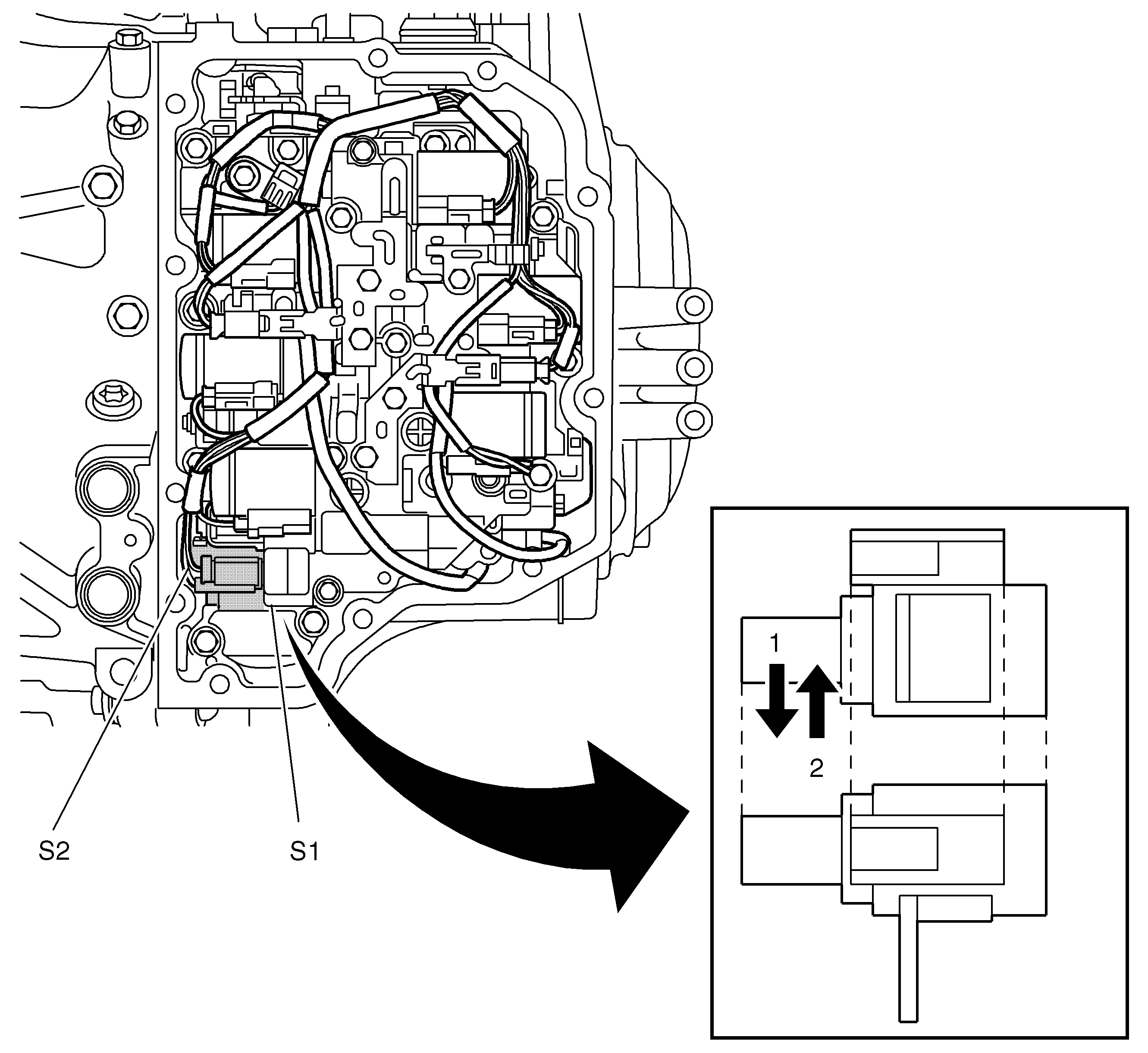
- On
- Off
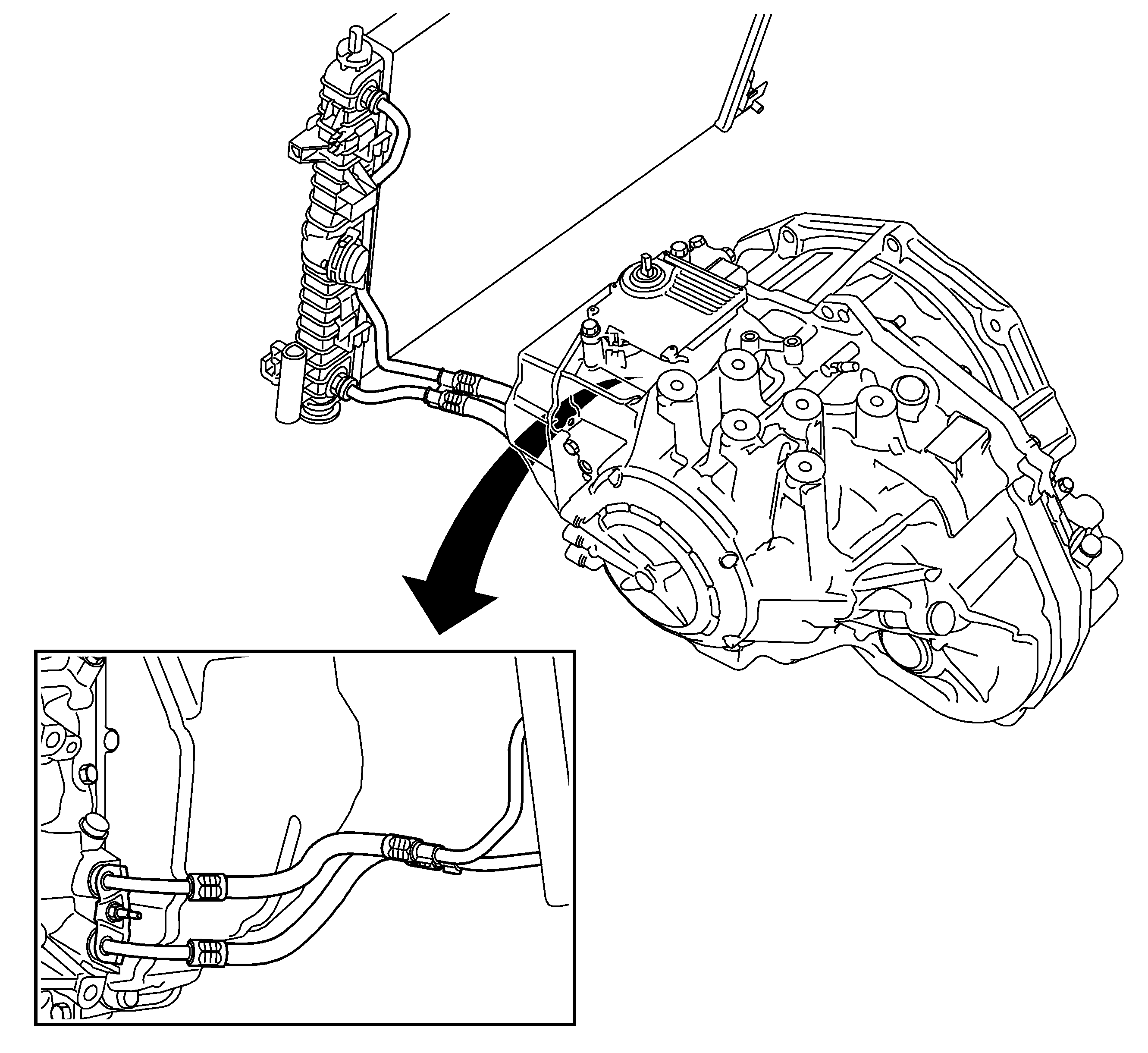
Cooling System
The automatic transmission has an oil cooler integrated in the engine radiator and constitutes one unit together with the gearbox. Fluid is circulated by the transmission fluid pump and carried via hydraulic hoses to the radiator and back to the transmission.
Control System
General
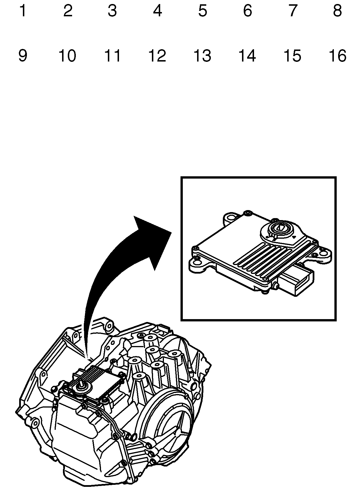
The gearbox is electronically controlled by a control unit (TCM, Transmission Control Module). The TCM is mounted directly on top of the gearbox and has one connector to the car's electrical system and one to the gearbox. The gear position sensor is Hall type and integrated in the control module. The TCM is mounted so that the selector lever shaft goes through the control module. The gear lever sensor position is calibrated in position N with a scan tool, there is no mechanical adjustment. TCM controls the solenoids to maintain or change gear. The solenoids are controlled with PWM (Pulse Width Modulation) to achieve a variable flow of oil.
Shifting
The determining factors for changing gear are two values; current gear and target gear. Current gear is the one engaged at the moment and the target gear is the one TCM wants to change to. As long as these to values are the same there will be no gear change. Gear changing is initiated only when the target gear differs from the current gear. It is mainly the vehicle speed and acceleration that determines the target gear in automatic transmissions. The vehicle speed is taken from a special sensor, output speed, while the acceleration is taken from the engine management system (ECM) via the high speed bus.
Gear changing must also follow a permitted schedule. If a direct change to the target gear is not present in the schedule, there will be an intermediate gear change. If, for example, the car is in 5th gear and the accelerator suddenly indicates a target gear of 2 (kickdown), the gear change will be 5 to 3 and 3 to 2. This is because 5 to 2 is not a valid gear change (refer to the section Mechanical for more information on this).
When a gear change is carried out, TCM will calculate a requested pressure for each solenoid circuit. The pressure is converted to a requested current that later results in a PWM ratio. The requested pressure is modulated according to a predetermined procedure so that the gear change is made comfortable without unnecessary wear. Current engine torque taken from ECM via the high speed bus is used for this purpose. A higher pressure is required for higher engine torque.
TCM reads the resulting current to each solenoid and can finely adjust the PWM ratio so that the requested pressure (current) agrees with the actual current. The gearbox does not have a pressure sensor so current pressure cannot be sent back to the control system. For this reason, the solenoids are calibrated very precisely.
Manual gear changing can be accomplished with the selector lever in position D using the up/down switch in the lever. A manual gear change must be fully completed before TCM will accept a new change command. The current gear is shown in DIC. The highest permitted gear for pulling away is 3rd. For safety's sake, there will be a change down from gear 6, 5 and 4 automatically after kickdown and engine speed below 2000 rpm.
TCM sends continuous information on the high speed bus concerning the engine torque allowed by the gearbox. When changing gear this value drops and ECM limits engine torque if it exceeds this value.
Lock up
The torque converter clutch is activated at steady speed in gears 3-6 when there is no need for any torque amplification. The slipping in procedure is regulated by comparing the speed on the input shaft with the engine speed obtained from ECM via the high speed bus. Lock up will not work at temperatures below 15°C. If the brake is depressed or acceleration increases, the function will be activated.
Safety features
A reverse detent function prevents reverse gear being engaged if the car is travelling faster than 7 km/h when the selector lever is moved from N to R. Overrevving in gear position M will be prevented by not allowing changing down to take place if the speed is too high.
Special gear change program
For high engine loads without a corresponding increase in speed one of two hill-climbing programs will be chosen. Gear changing is done at higher engine speeds and the gear will remain engaged for longer periods until the extra load ceases. These gearchange programs are used to avoid changing up and down unnecessarily, e.g. when driving up long inclines with trailer and to avoid overheating the gearbox oil. The Sport Mode can be engaged by a switch. Upon detecting the sport mode request TCM adapts the shift lines in order to enable a more progressive driving. Special gear change programs are not activated at speeds above 150 km/h. If a special gear change program is active when the speed increases to over 150 km/h, the program will continue, however, until the load has normalized.
Diagnostics
The control module has diagnosis for internal faults. The solenoids are diagnosed with respect to open circuits and short circuits. They are also pulsed and the inductive voltage peak is analyzed to make sure the coil is not partially shorted. The speed sensor and temperature sensor circuits and plausibility are checked. High speed bus communication is checked to make sure no necessary messages are missing. Mechanical faults (slipping or wrong gear) are detected by comparing speed sensor values with the engaged gear.
Limp home
If the power supply to TCM or to the solenoids is cut, the car can still be driven. Gear position D/M will give 2nd gear and P-R-N will work as normal but the gear will be engaged roughly as there is no regulation.
In case of a major fault in the gearbox, mechanical or electrical, TCM will cut the supply to the solenoids in a controlled manner. In most cases, the control module will attempt to maintain the current gear until the car has stopped. Subsequently, the control module will attempt to engage 2nd gear if D/M is selected. After this, the supply to the solenoids will be cut and the gearbox will lose all electrical control.
If an invalid gear ratio or the wrong gear is detected, the engine torque will be limited to 170 N·m in reverse and 150 N·m forward. For other faults, the torque will be limited to higher values depending on failure.
Towing
The car may only be towed with the front pointing in the direction of travel. The selector lever must be in position N. National regulations concerning towing speeds must be adhered to. If legislation allows, the highest permitted towing speed is 50 km/h. The longest permitted towing distance is 50 km. If the car should require towing for longer distances, the front wheels must be raised from the ground.
The engine cannot be started by pushing or towing the car.
