Cooling System Draining and Filling GE-47716
Special Tools
| • | J 26568 Coolant and Battery Fluid Tester |
| • | J 42401 Radiator Pressure Adapter |
Draining Procedure
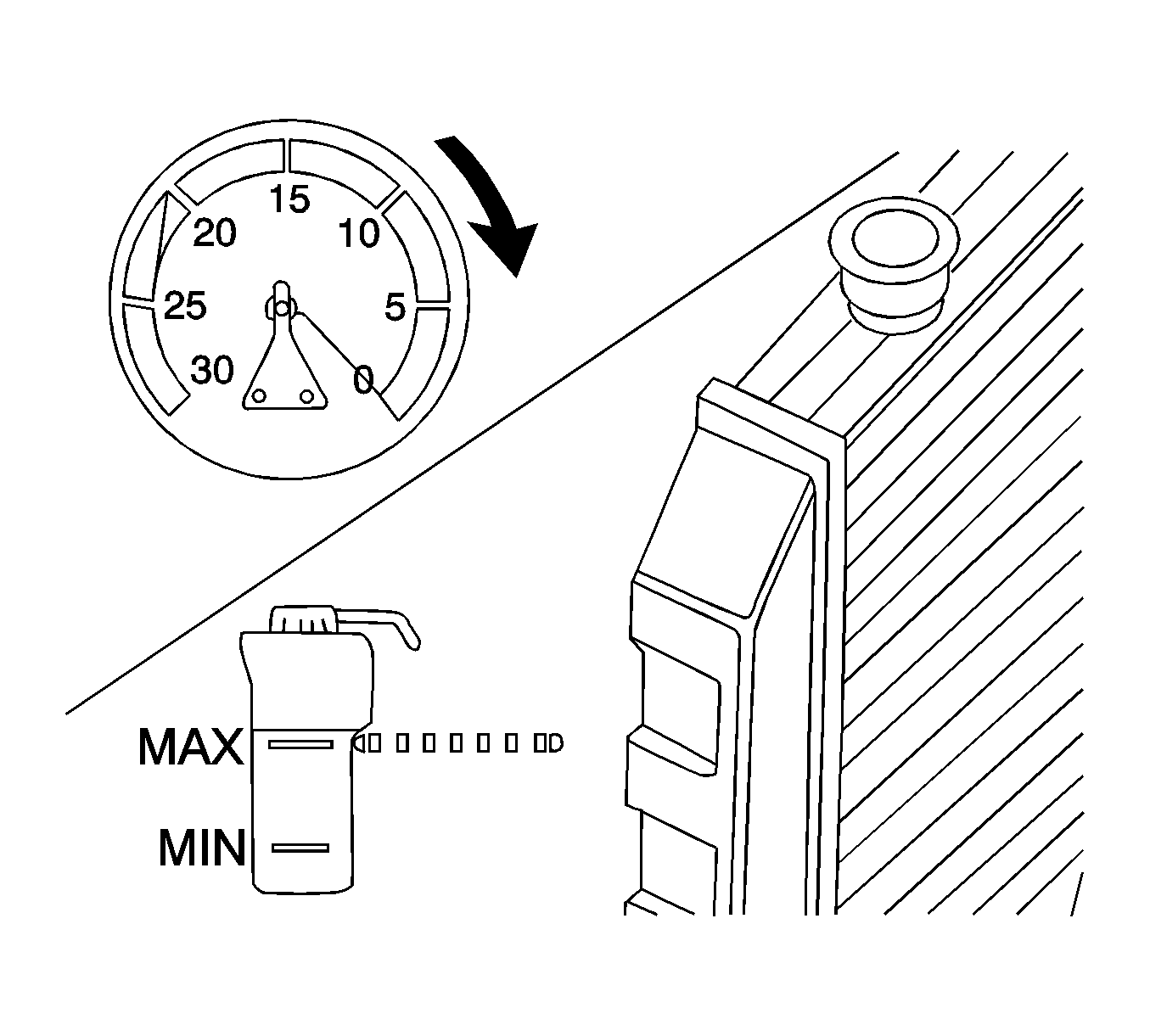
- Remove the pressure cap.
- Raise and support the vehicle. Refer to Lifting and Jacking the Vehicle .
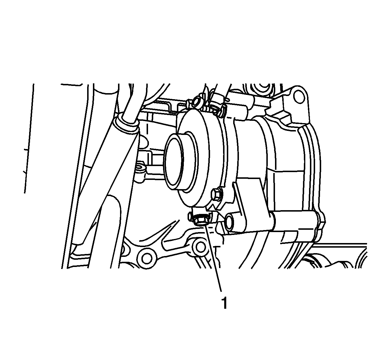
- Place a drain pan under the right side lower radiator mount.
- Open the radiator drain cock.
- Drain the cooling system.
- If a complete block drain is required, place a drain pan under the water pump drain.
- Remove the water pump drain plug (1).
- Drain the cooling system.
- Inspect the appearance of the engine coolant for discoloration:
Caution: To avoid being burned, do not remove the radiator cap or surge tank cap while the engine is hot. The cooling system will release scalding fluid and steam under pressure if radiator cap or surge tank cap is removed while the engine and radiator are still hot.
| • | Discolored--Follow the flush procedure. Refer to Flushing . |
| • | Normal in appearance--Follow the filling procedure. |
Vac-N-Fill Procedure
- Close the radiator drain cock by hand.
- Install the water pump drain plug if removed during the draining process (1).
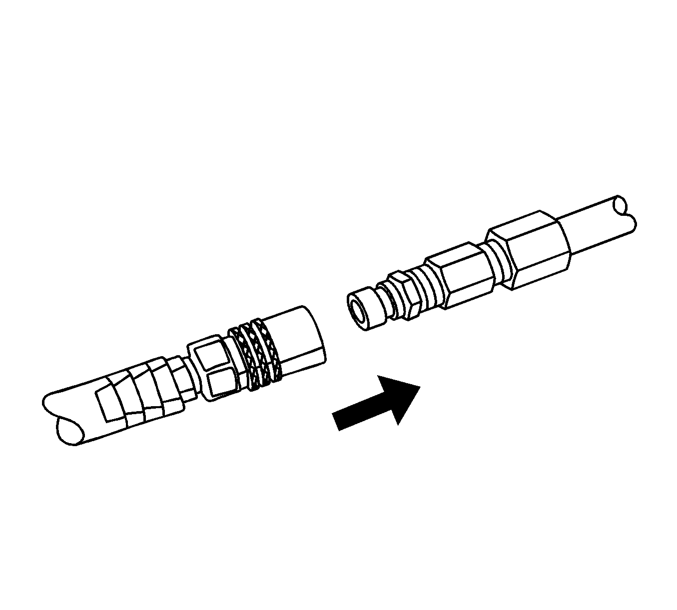
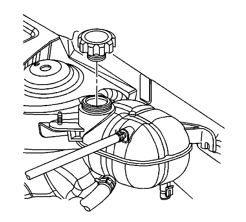
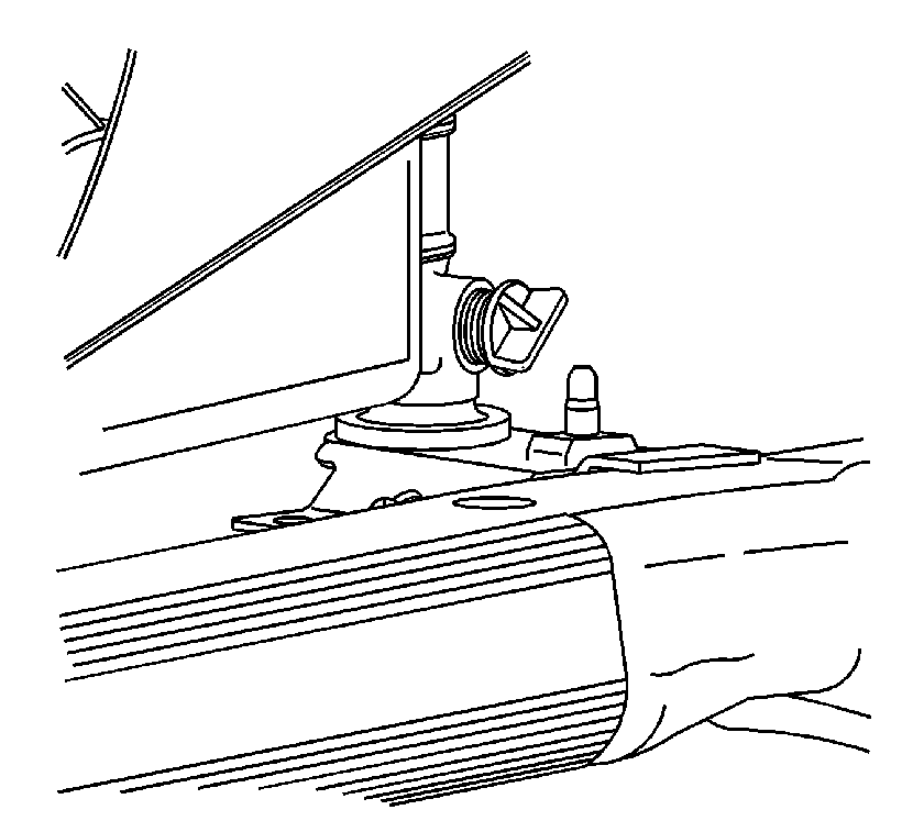
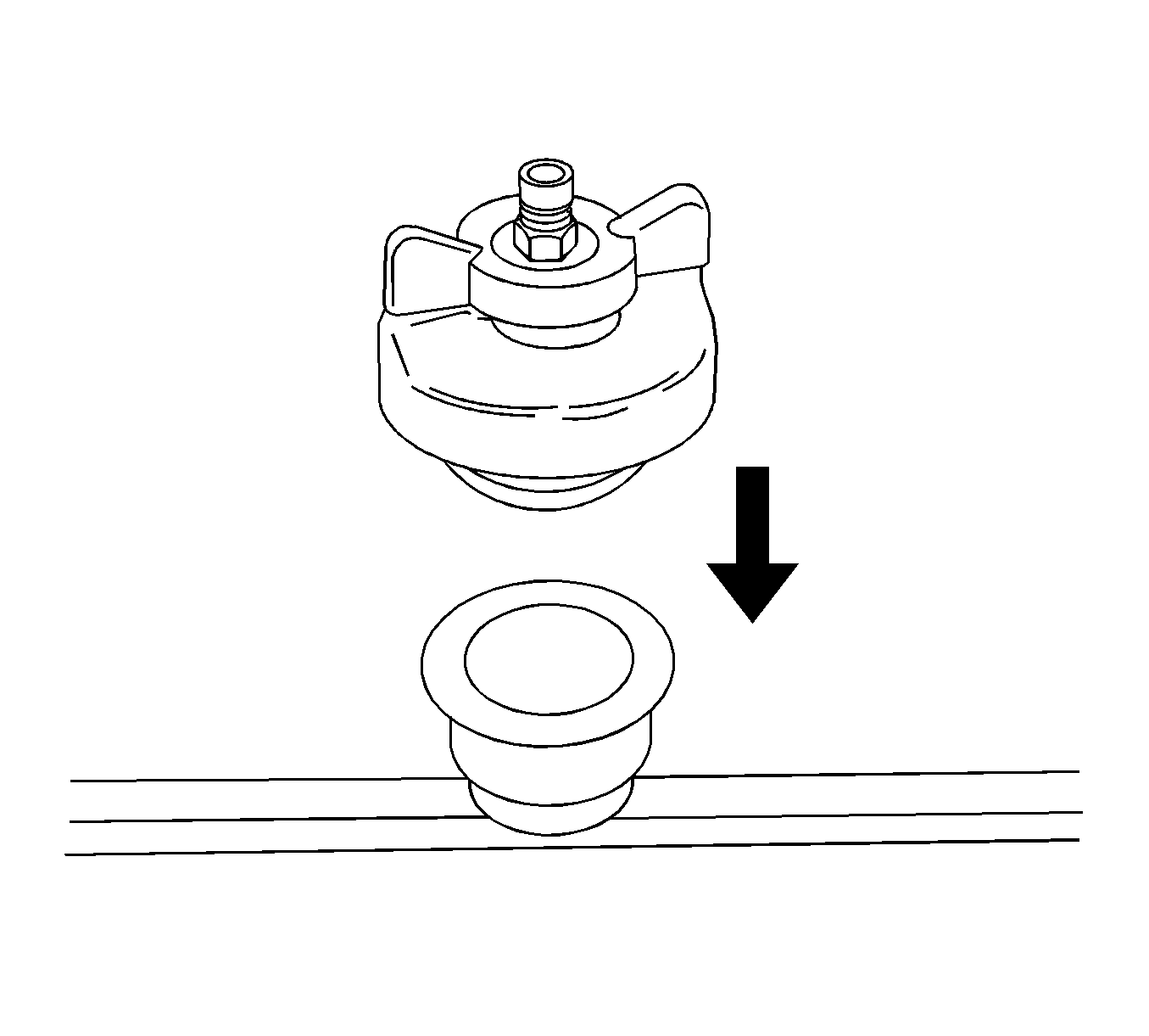
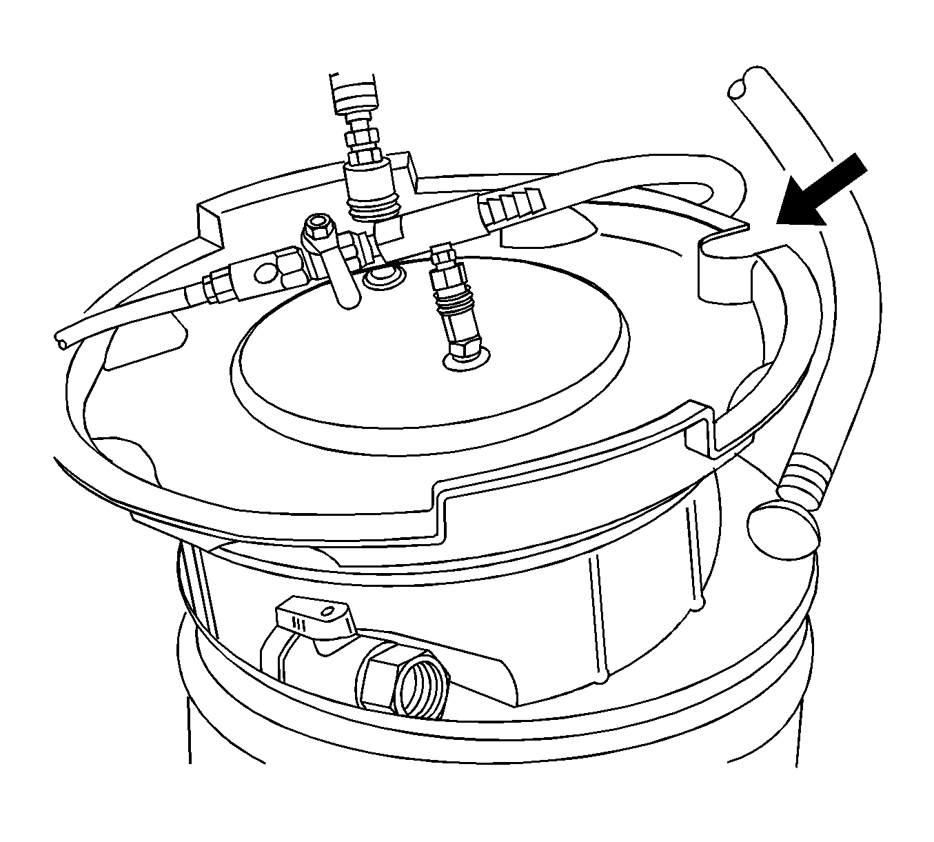
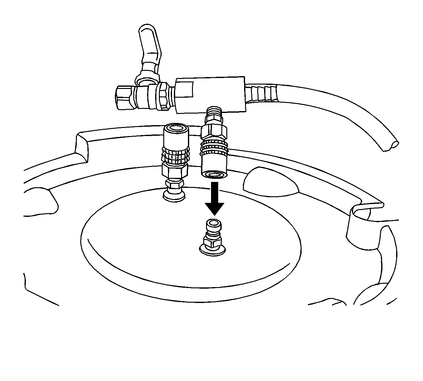
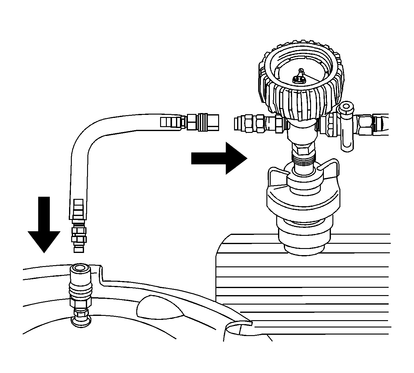
- Install J-42401-2 into the surge tank fill neck.
- Install J-42401-3 to the surge tank fill neck.
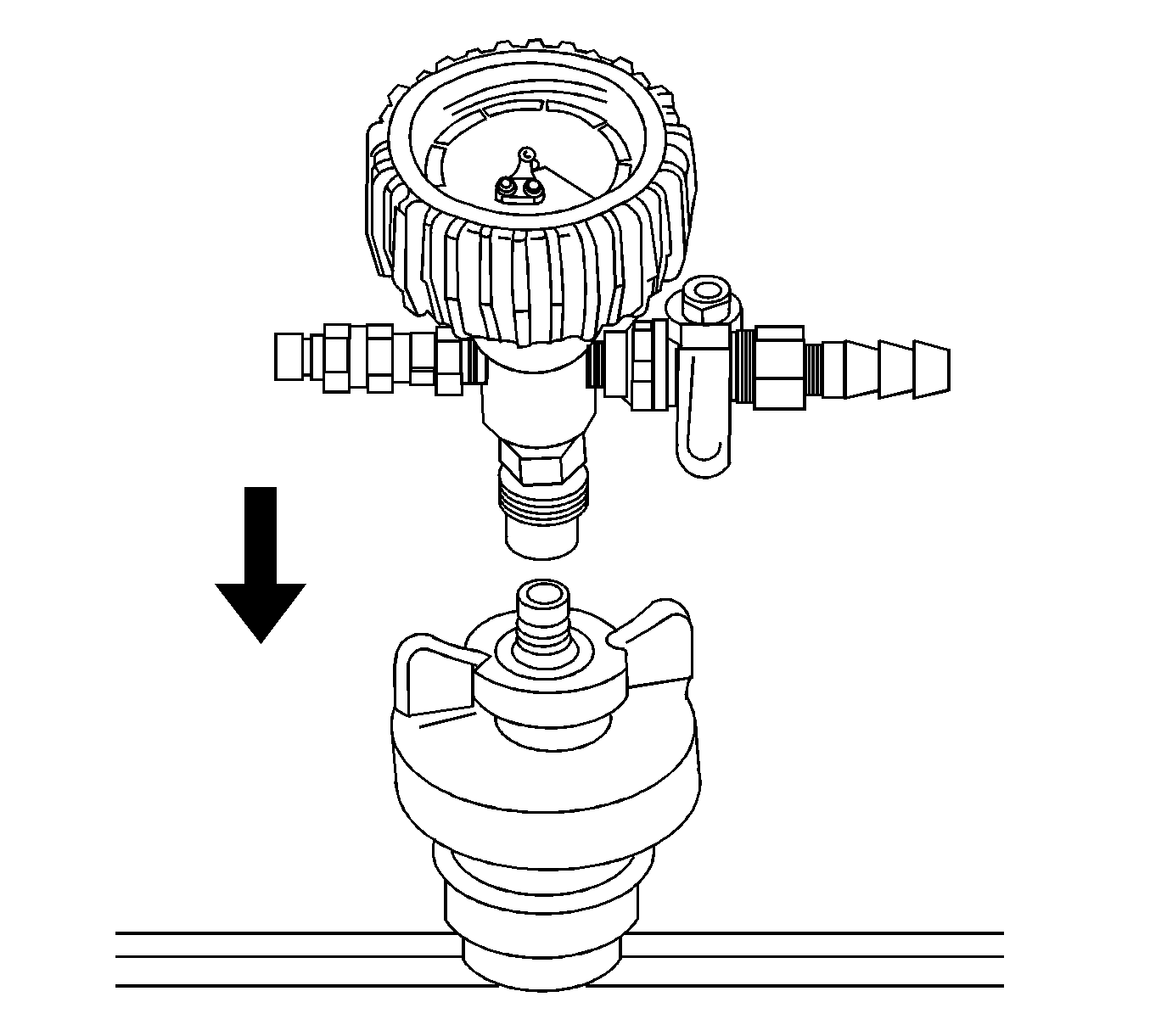
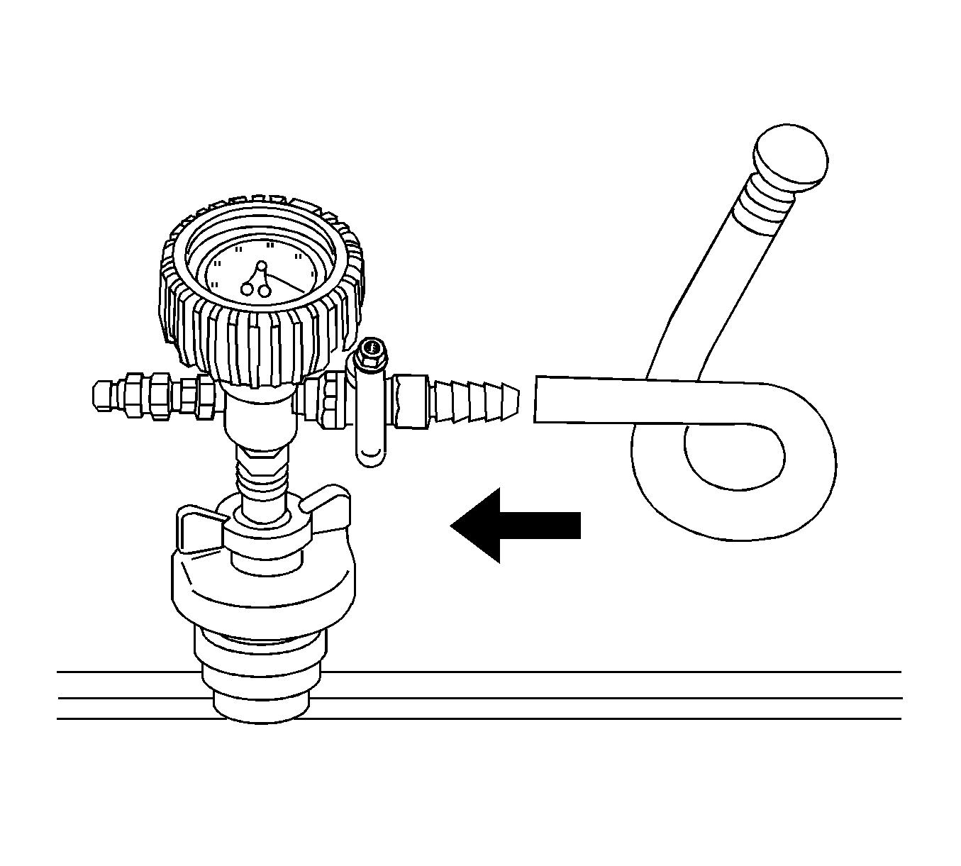
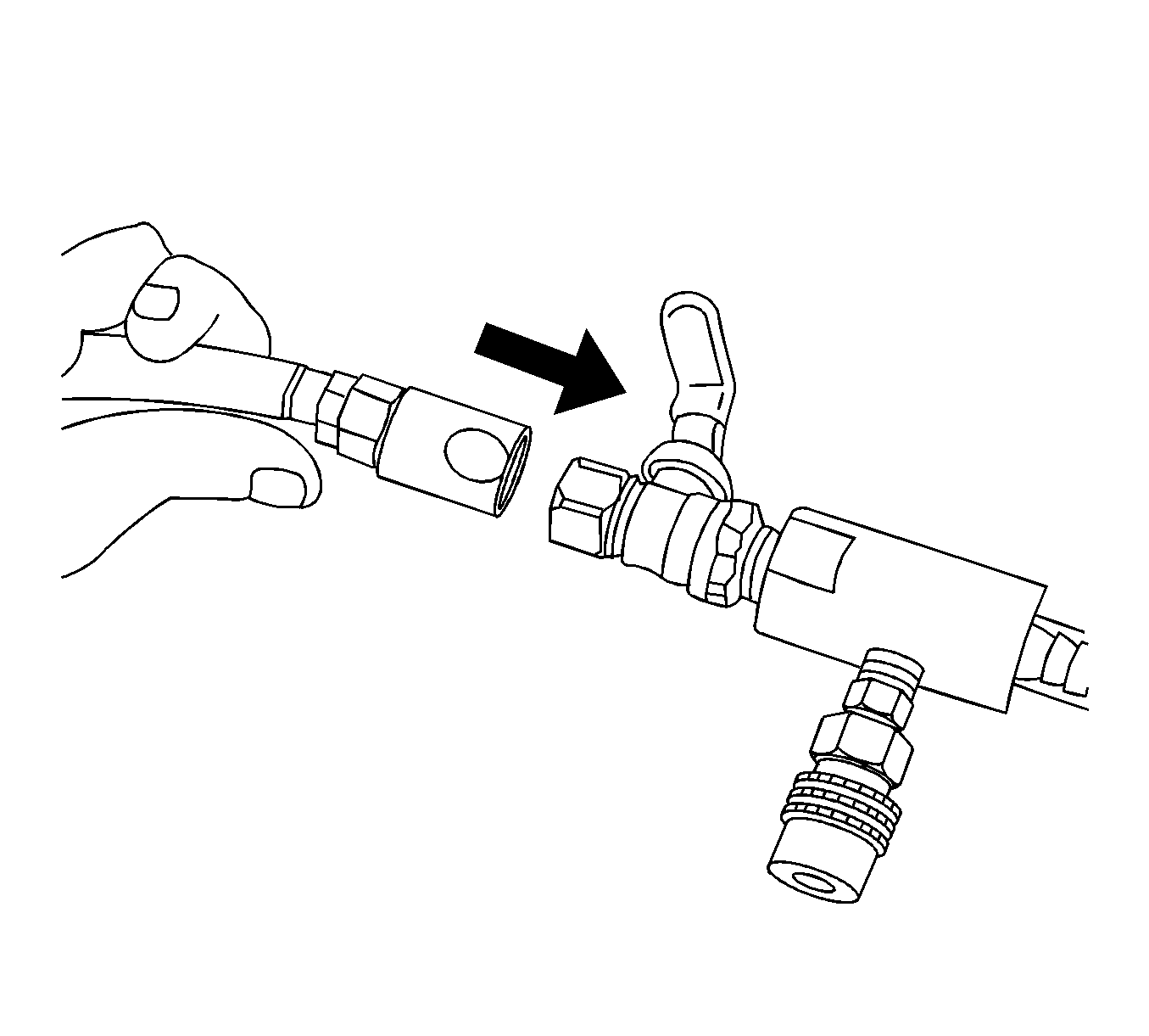
- Attach the Vac N Fill cap to the J-42401-3.
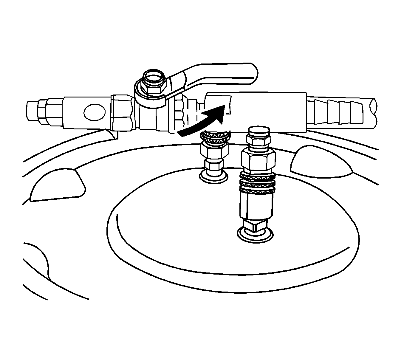
- Attach the vacuum gauge assembly to the Vac N Fill cap.
- Attach the fill hose to the barb fitting on the vacuum gauge assembly.
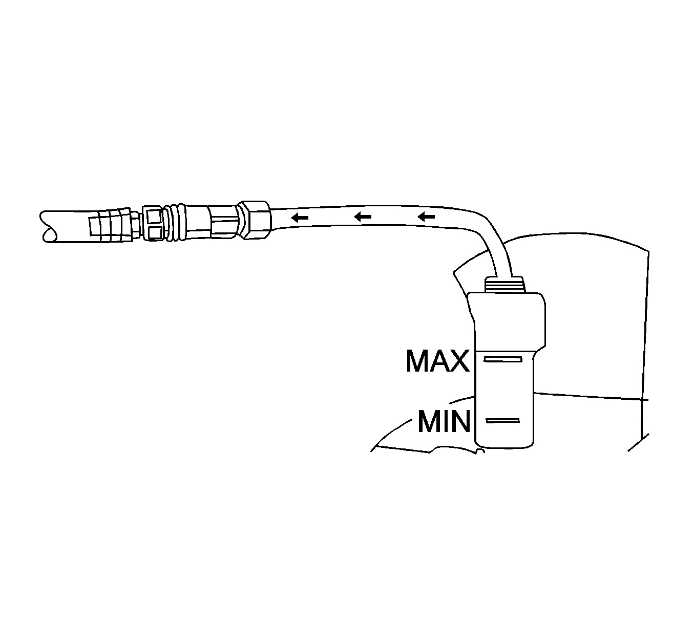
- Pour the coolant mixture into the graduated reservoir.
- Place the fill hose in the graduated reservoir.
- Install the vacuum tank on the graduated reservoir with the fill hose routed through the cut-out area in the vacuum tank.
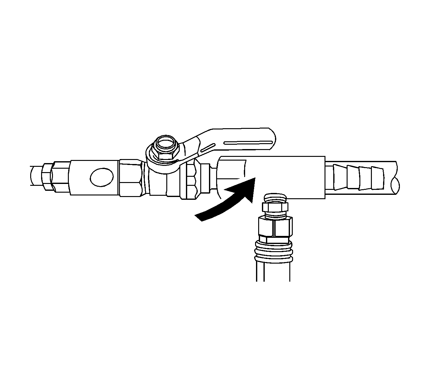
- Attach the venturi assembly to the vacuum tank.
- Attach a shop air hose to the venturi assembly.
- Attach the vacuum hose to the vacuum gauge assembly and the vacuum tank.
- Open the valve on the venturi assembly. The vacuum gauge will begin to rise and a hissing noise will be present.
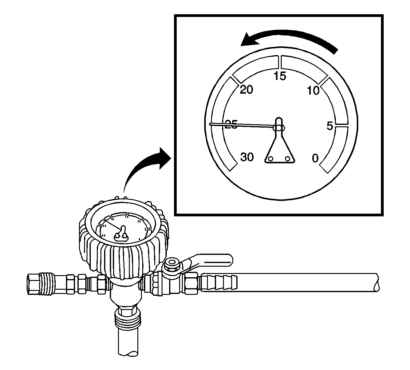
- Continue to draw vacuum until the needle stops rising. This should be 610-660 mm Hg (24-26 in Hg).
- To aid in the fill process, position the graduated reservoir above the surge tank.
- Slowly open the valve on the vacuum gauge assembly. When the coolant reaches the top of the fill hose, close the valve. This will eliminate air from the fill hose.
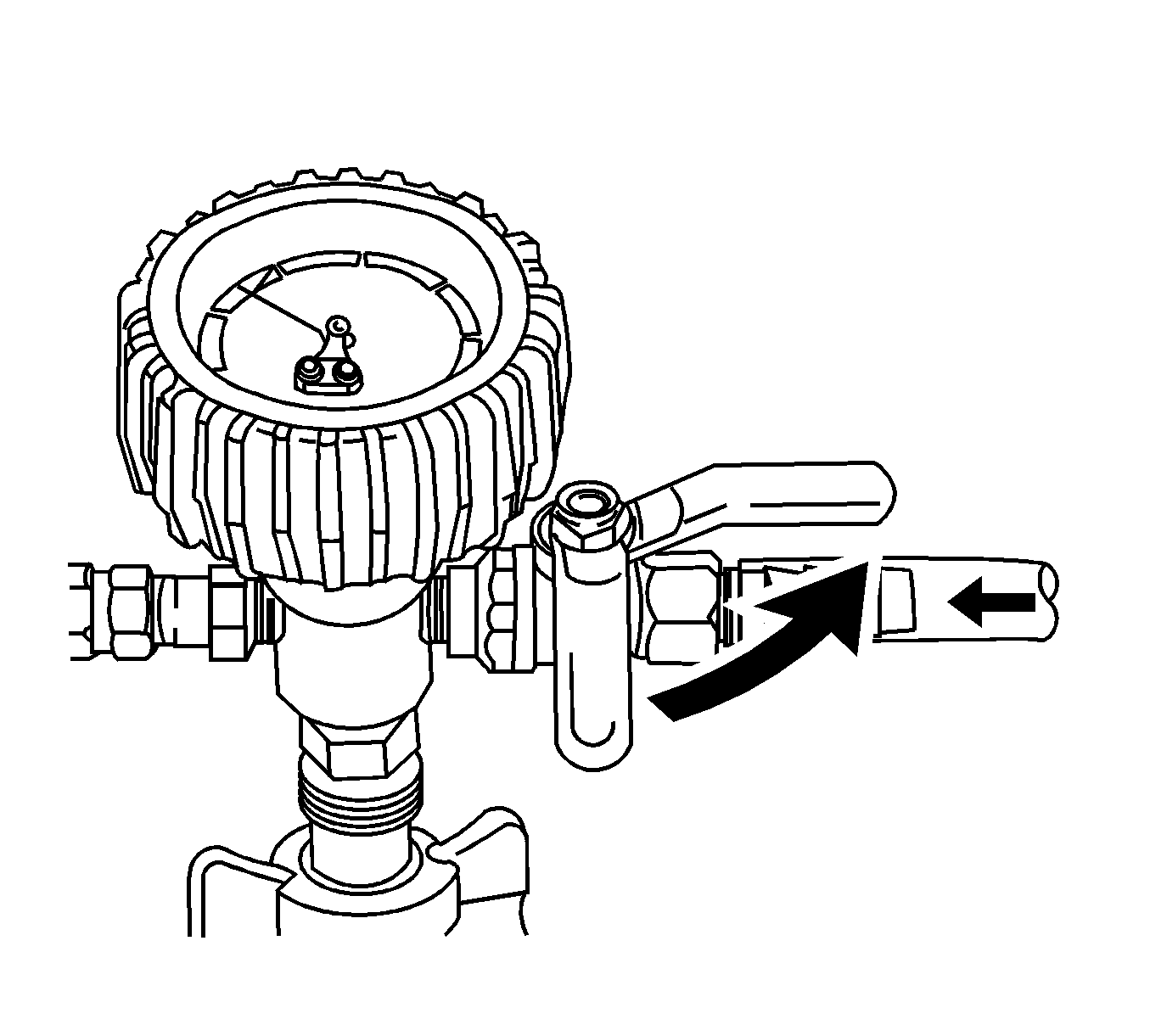
- Close the valve on the venturi assembly.
- If there is a suspected leak in the cooling system, allow the system to stabilize under vacuum and monitor for vacuum loss.
- Open the valve on the vacuum gauge assembly. The vacuum gauge will drop as coolant is drawn into the system.
- Once the vacuum gauge reaches zero, close the valve on the vacuum gauge assembly and repeat steps 10-16.
- Detach the Vac N Fill cap from the vehicle's coolant fill port.
- Add coolant to the system as necessary.
- Inspect the concentration of the coolant mixture using J 26568 .
- Detach the vacuum hose from the vacuum gauge assembly.
- Attach the extraction hose to the vacuum hose.
- Open the valve on the venturi assembly to start a vacuum draw.
- Use the extraction hose to draw out coolant to the proper level.
- The vacuum tank has a drain valve on the bottom of the tank. Open the valve to drain coolant from the vacuum tank into a suitable container for disposal.
Notice: The procedure below must be followed. Improper coolant level could result in a low or high coolant level condition, causing engine damage.
Notice: Refer to Fastener Notice in the Preface section.
Tighten
22 Nm (16 lb ft)
Important: To prevent boiling of the coolant/water mixture in the vehicle’s cooling system, do not apply vacuum to a cooling system above 49° C (120° F). The tool will not operate properly when the coolant is boiling.
Ensure that the valve is closed.
Important: Use a 50/50 mixture of DEX-COOL antifreeze and clean, drinkable water.
Always use more coolant than necessary. This will eliminate air from being drawn into the cooling system.Important: Prior to installing the vacuum tank onto the graduated reservoir, ensure that the drain valve located on the bottom of the tank is closed.
Ensure the valve on the venturi assembly is closed.
Cooling hoses may start to collapse. This is normal due to vacuum draw.
If vacuum loss is observed, refer to Loss of Coolant .
Important: After filling the cooling system, the extraction hose can be used to remove excess coolant to achieve the proper coolant level.