POOR FIT AND/OR RETENTION OF THE KNEE BOLSTER

SUBJECT POOR FIT OF THE KNEE BOLSTER (PROCEDURE TO REPAIR)
MODELS/YEARS 1990 TORONADO AND TROFEO
This bulletin supercedes Dealer Technical Bulletin 90-T-42 (078303) and Step 16 of Dealer Technical Bulletin 90-T-40 (078302).
Some 1990 Toronados and Trofeos may experience a condition of poor fit of the knee bolster. To repair this condition use the following procedure.
To perform the outlined procedure the following will be needed:
1 . Knee bolster (obtained from GMSPO; refer to chart for colors and part numbers).
2. Small square coarse/medium coarse hand file.
3. One knee bolster clip, part number 3523076 (if vehicle's VIN is prior to LU302111).
4. One "J" nut, part number 52351724 (if vehicle's VIN is prior to LU302111).
Parts are currently available from GMSPO.
PROCEDURE:
1 . Remove screw(s) from lower edge of knee bolster.
2. Remove the knee bolster and discard.
3. Remove the instrument panel/steering column reinforcement plate. Refer to Section 8C of the Service Information Manual.
4. Remove instrument panel cluster trim plate.
5. Remove right side switch assembly.
6. Remove instrument panel cluster assembly.
7. Remove multi-function lever by pulling straight out. Let it hang freely.
8. Unscrew the tilt lever and remove.
9. Remove the dual lock fastener from the instrument panel carrier and any adhesive residue left behind.
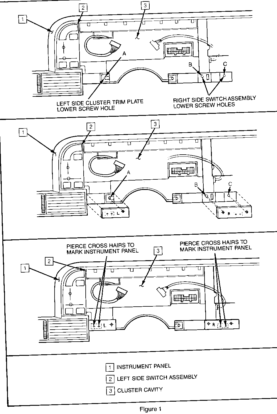
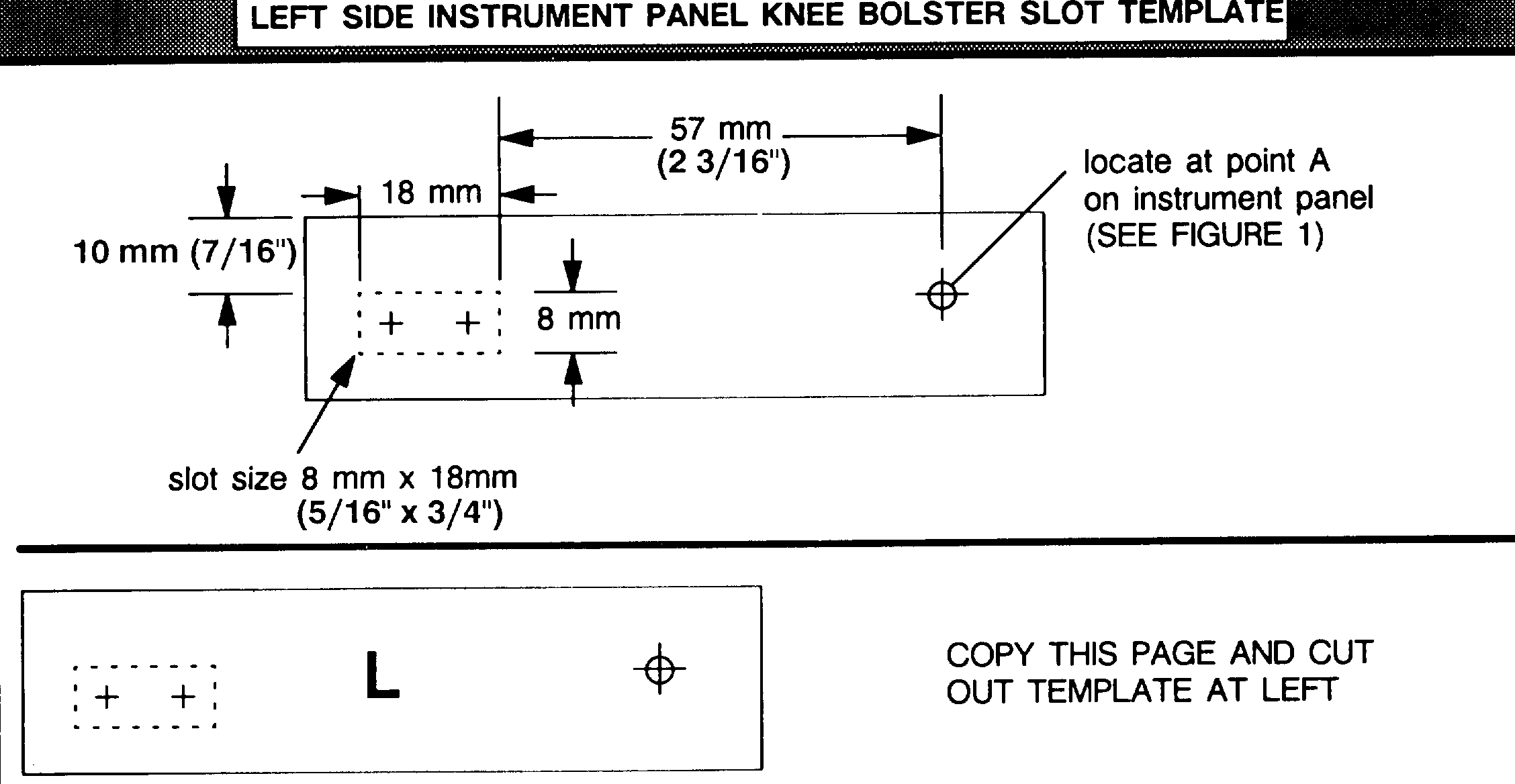
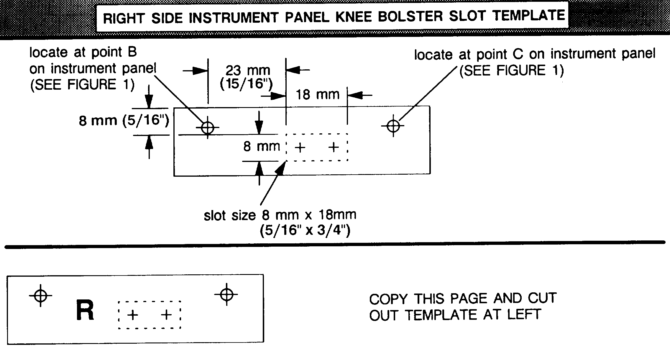
10. Locate left side slot template on instrument panel and secure with tape. Refer to Figure 1 and the template.
11. If the instrument panel has a hole in the slot location from the hook and loop fastener, skip steps 12, 14, and 15.
12. Pierce the cross hairs of the template in the slot area with sharp awl to mark instrument panel. Refer to Figure 1.
13. Cut out the dotted portion (slot) of the template with a sharp utility knife.
NOTE: Care must be exercised to accurately cut the dotted portion of the template. Accurate slot size is critical to proper knee bolster retention.
14. Drill two 8mm (5/16") holes at the two pierce marks made in step 9.
NOTE: Care must be exercised to accurately locate and drill these holes. Accurate slot size is critical to proper knee bolster retention.
15. File out the bridge of material left between the two drilled holes taking care not to damage the instrument panel.
16. File out the remainder of material within the template opening.
NOTICE: Retention of the knee bolster is dependent upon slot opening height. Maximum slot height is 8mm (5/16"). Filing a larger slot will damage the instrument panel beyond repair and will not provide sufficient retention of the knee bolster.
17. Locate right side slot template on instrument panel and secure with tape. Refer to Figure 1 and the template.
18. Repeat steps 11 through 16 similarly for the right side slot.
19. Remove templates.
20. Install right side switch assembly.
21. Install instrument panel cluster.
22. Install instrument panel cluster trim plate.
23. Install tilt lever.
24. Install multi-function lever.
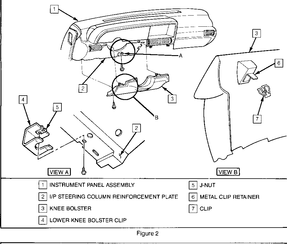
25. Install knee bolster lower clip to instrument panel/steering column reinforcement plate (if VIN is prior to LU302111). Refer to Figure 2.
26. Install new knee bolster. Refer to Figure 2.
Line up the two clips at the top of the knee bolster with the two slots in the instrument panel carrier. At the same time, line up the lower right knee bolster edge (protruding) with the lower clip.
Continue forward with the knee bolster until the two top clips are fully seated and the lower right knee bolster edge is supported in the lower clip.
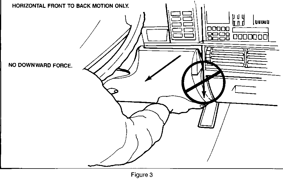
NOTICE: When removing the knee bolster, do not exert any downward force at the upper edge of the knee bolster on either side of the steering column. Only a front-to-back horizontal force should be used to unseat the two top clips from the instrument panel. Failure to follow these instructions may damage the knee bolster beyond repair. Update page 8C- 6 of the Service Information Manual with this information. Refer to Figure 3.
27. Install the screw to the lower left knee bolster edge. Refer to Figure 2.
WARRANTY INFORMATION:
Labor Operation Number: T6473 Labor Time: 1.0 hour Trouble Code: 92
Parts are currently available from GMSPO.
USE THIS CHART TO DETERMINE PART NUMBER
SERVICE PART COLOR PART NUMBER -------------- ------------------ -----------
(151) DARK SLATE GRAY 3524334 (191) BLACK 3524335 KNEE BOLSTER (201) VERY DARK SAPPHIRE 3524336 (651) DARK ANTELOPE 3524337 (68I) DARK AUBURN 3524338 (781) GARNET RED 3524339
KNEE BOLSTER CLIP N/A 3523076
"J" NUT N/A 52351724
General Motors bulletins are intended for use by professional technicians, not a "do-it-yourselfer". They are written to inform those technicians of conditions that may occur on some vehicles, or to provide information that could assist in the proper service of a vehicle. Properly trained technicians have the equipment, tools, safety instructions and know-how to do a job properly and safely. If a condition is described, do not assume that the bulletin applies to your vehicle, or that your vehicle will have that condition. See a General Motors dealer servicing your brand of General Motors vehicle for information on whether your vehicle may benefit from the information.
