For 1990-2009 cars only
Removal Procedure
- Remove the instrument panel (I/P) knee bolster. Refer to Knee Bolster Replacement in Instrument Panel, Gages and Console.
- Remove the ignition lock cylinder. Refer to Ignition Lock Cylinder Replacement in Steering Wheel and Column.
- Remove the trim cover from the upper steering column. Refer to Steering Column Trim Covers Replacement in Steering Wheel and Column.
- Disconnect the electrical connector at the base of the steering column.
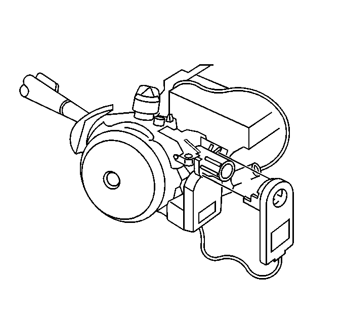
- Pull the theft deterrent control module from the ignition lock cylinder housing.
- Remove the electrical connector and wires from the steering column.
- Remove the theft deterrent control module from the vehicle.

Installation Procedure
- Install the theft deterrent control module to the vehicle.
- Install the electrical connector and wires to the column.
- Slide the theft deterrent control module over the ignition lock cylinder housing.
- Connect the electrical connector at the base to the steering column.
- Install the trim cover to the upper steering column. Refer to Steering Column Trim Covers Replacement in Steering Wheel and Column.
- Install the ignition lock cylinder. Refer to Ignition Lock Cylinder Replacement in Steering Wheel and Column.
- Install the I/P knee bolster. Refer to Knee Bolster Replacement in Instrument Panel, Gages and Console.
- Program the theft deterrent system. Refer to Programming Theft Deterrent System Components .

