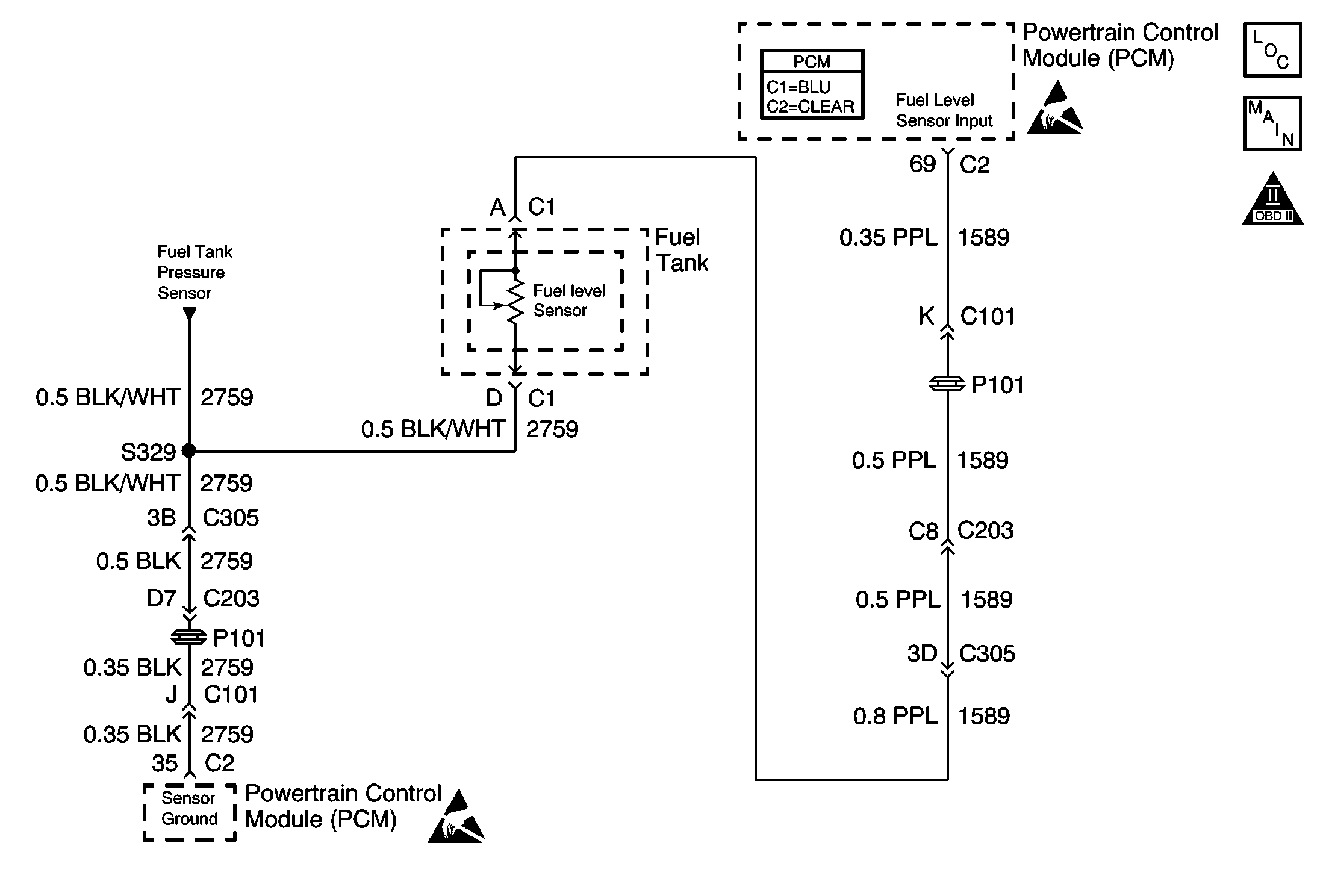
Circuit Description
The PCM uses the fuel level input in order to calculate the expected vapor pressures within the fuel system. These vapor pressures vary as the fuel level changes. The vapor pressure is critical in determining if the Evaporative Emissions System is operating properly. The PCM also uses the fuel level in order to determine if the fuel level is too high or too low to be able to accurately detect EVAP system malfunction.
Conditions for Running the DTC
| • | The ignition is ON. |
| • | System voltage is between 10.0 and 18.0 volts. |
Conditions for Setting the DTC
The Fuel Level Sensor should be greater than 98% for greater than 25 seconds.
Action Taken When the DTC Sets
The PCM stores conditions which were present when the DTC set as Failure Records only. This information will not be stored as Freeze Frame Records.
Conditions for Clearing the MIL/DTC
| • | The DTC becomes history when the conditions for setting the DTC are no longer present. |
| • | The history DTC clears after 40 malfunction free warm-up cycles. |
| • | The PCM receives a clear code command from the scan tool. |
Diagnostic Aids
| • | An intermittent problem may be caused by the following conditions: |
| - | Poor electrical connection |
| - | Rubbed through wire insulation |
| - | A wire that is broken inside the wire insulation |
| • | Any circuitry, that is suspected as causing the intermittent complaint, should be thoroughly checked for the following conditions: |
| - | Backed out terminals |
| - | Improper mating |
| - | Broken locks |
| - | Improperly formed or damaged terminals |
| - | Poor terminal to wire connection |
Many situations may lead to an intermittent condition. Perform each inspection or test as directed.
Important: : Remove any debris from the connector surfaces before servicing a component. Inspect the connector gaskets when diagnosing or replacing a component. Ensure that the gaskets are installed correctly. The gaskets prevent contaminate intrusion.
| • | Loose terminal connection |
| - | Use a corresponding mating terminal to test for proper tension. Refer to Testing for Intermittent Conditions and Poor Connections , and to Connector Repairs in Wiring Systems for diagnosis and repair. |
| - | Inspect the harness connectors for backed out terminals, improper mating, broken locks, improperly formed or damaged terminals, and faulty terminal to wire connection. Refer to Testing for Intermittent Conditions and Poor Connections , and to Connector Repairs in Wiring Systems for diagnosis and repair. |
| • | Damaged harness--Inspect the wiring harness for damage. If the harness inspection does not reveal a problem, observe the display on the scan tool while moving connectors and wiring harnesses related to the sensor. A change in the scan tool display may indicate the location of the fault. Refer to Wiring Repairs in Wiring Systems for diagnosis and repair. |
| • | Inspect the powertrain control module (PCM) and the engine grounds for clean and secure connections. Refer to Wiring Repairs in Wiring Systems for diagnosis and repair. |
If the condition is determined to be intermittent, reviewing the Snapshot or Freeze Frame/Failure Records may be useful in determining when the DTC or condition was identified.
Test Description
Number(s) below refer to the step number(s) on the Diagnostic Table:
-
The Powertrain OBD System Check prompts the technician to complete some basic checks and store the freeze frame and failure records data on the scan tool if applicable. This creates an electronic copy of the data taken when the malfunction occurred. The information is then stored in the scan tool for later reference.
-
Tests for proper operation of the fuel level circuit in the high voltage range.
-
Tests for proper operation of the fuel level circuit in the low voltage range. If the fuse in the jumper opens when you perform this test, the signal is sorted to voltage.
-
Replacement PCM must be reprogrammed and the crankshaft position system variation procedure must be performed. Refer to the latest Techline information for PCM reprogramming and also refer to the CKP System Variation Learn Procedure for the Crankshaft Position System Variation Procedure.
Step | Action | Value(s) | Yes | No |
|---|---|---|---|---|
Did you preform the Powertrain On-Board Diagnostic (OBD) System Check? | -- | |||
|
Important: If a 5 volt referance DTC sets, diagnosis this DTC first.
Does the scan tool indicate that the Fuel Level parameter is greater than the specified value? | 98% | Go to Diagnostic aids | ||
Important: If the fuse opens, locate a short to ground. Does the scan tool indicate that the Fuel Level parameter is less than the specified value? | 3.5% | |||
4 | Test the Fuel Level signal circuit for a short to voltage, high resistance or a open. Refer to Testing for Intermittent Conditions and Poor Connections and Wiring Repairs . Did you find and correct the condition? | -- | ||
5 | Test the Fuel Level ground circuit for a high resistance or an open. Refer to Testing for Intermittent Conditions and Poor Connections and Wiring Repairs Did you find and correct the condition? | -- | ||
6 | Test for poor connections at the fuel level sensor harness connector. Testing for Intermittent Conditions and Poor Connections and Connector Repairs . Did you find and correct the condition? | -- | ||
7 | Test the Fuel Level sensor circuit and Fuel Level ground circuit for poor connections at the PCM Did you find and correct the condition? | -- | ||
8 | Replace the Fuel Level Sensor. Refer to Fuel Level Sensor Replacement . Did you complete the replacement? | -- | -- | |
|
Important: : The replacement PCM must be programmed. Replace the PCM. Refer to Powertrain Control Module Replacement/Programming . Did you complete the replacement? | -- | -- | ||
10 |
Does the scan tool indicate that this diagnostic has ran and passed? | -- | System OK |
