Removal Procedure
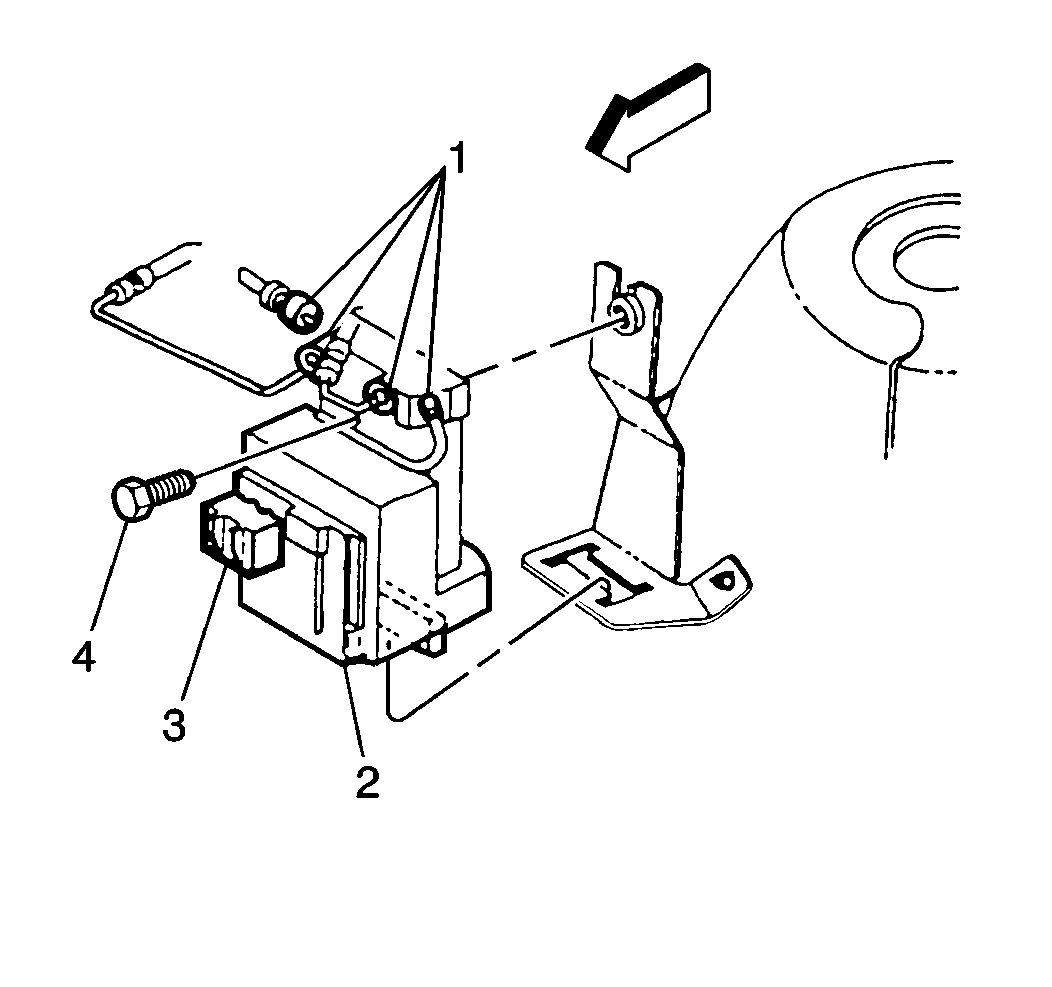
- Remove the TCS modulator assembly (2) from bracket. Refer to Traction Control System Modulator/Motor Pack Replacement .
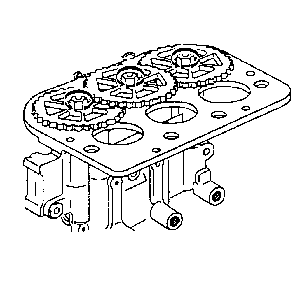
- Remove the three Torx® head screws that attach the gear cover to TCS hydraulic modulator.
- Remove the two Torx® head screws that attach the motor pack to TCS hydraulic modulator .
- Separate the motor pack from the modulator.
- Remove the gears from the modulator.
- Remove two modulator drive gears from the modulator drive shaft retaining nuts.
Caution: The modulator drive gears are under spring load and will turn during disassembly. After removing brake modulator drive gear cover, exercise extreme care not to place fingers into the gear set, since fingers can be pinched by rotating gears.
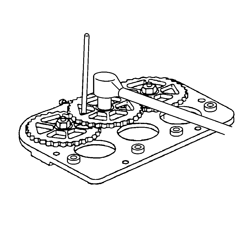
Notice: Do not allow gear to turn while removing the retaining nut, since the modulator piston can hit the top of the modulator bore, damaging the piston. Place a screwdriver through the holes in the gears (not between the gears) into the recessed hole in the modulator base. This will prevent the gear from turning, aiding in gear removal.
Important: Do not repair damaged motor pack or brake modulator. Other than modulator drive gears replacement repair of the motor pack and brake modulator assemblies is not authorized. Do not oil or lubricate the gears on the motor pack.
Important: Use care when handling the motor pack. Replace the motor pack if the motor pack is dropped or damaged during handling.
Installation Procedure
- Position the modulator drive gears onto the modulator drive shaft.
- Install two gear retaining nuts.
- With the modulator positioned upside down and the gears facing you and rotate each TCS modulator gear clockwise until movement stops.
- Position the motor pack onto the modulator aligning the two motor pack gears with the modulator gears.
- Install two motor pack to modulator Torx® head screws.
- Install the gear cover onto the modulator then install 3 Torx® head screws.
- Install the TCS modulator/motor pack assembly. Refer to Traction Control System Modulator/Motor Pack Replacement .
Notice: Do not allow gear to turn while removing the retaining nut, since the modulator piston can hit the top of the modulator bore, damaging the piston. Place a screwdriver through the holes in the gears (not between the gears) into the recessed hole in the modulator base. This will prevent the gear from turning, aiding in gear removal.
Notice: Use the correct fastener in the correct location. Replacement fasteners must be the correct part number for that application. Fasteners requiring replacement or fasteners requiring the use of thread locking compound or sealant are identified in the service procedure. Do not use paints, lubricants, or corrosion inhibitors on fasteners or fastener joint surfaces unless specified. These coatings affect fastener torque and joint clamping force and may damage the fastener. Use the correct tightening sequence and specifications when installing fasteners in order to avoid damage to parts and systems.
Tighten
Tighten the nuts to 8.5 N·m (75 lb in).
Rotating the modulator gears will cause the following conditions:
| • | The pistons on the TCS modulator will be positioned very close to the bottom of the modulator bore. |
| • | The brake bleeding procedure is simplified. |
Important: Use care when handling the motor pack. Replace the motor pack if the motor pack is dropped or damaged during handling.
Tighten
Tighten the Torx® head screws to 4.5 N·m (40 lb ft).
Tighten
Tighten the Torx® head screws to 4 N·m (45 lb in).
