SERV. MANUAL UPDATE-SEC. 10-10 DRIVER'S SEAT ADJ. SWITCH RPL.

SUBJECT: DRIVER'S SEAT ADJUSTER SWITCH REPLACEMENT
VEHICLES AFFECTED: 1990-93 "U" VANS WITH POWER SEATS (RPO AC3)
Procedures in this bulletin serve as an addition to existing seat service information found in 1 990-93 Chevrolet Lumina APV, Pontiac Trans Sport and Oldsmobile Silhouette Service Manual Sections 10-10.
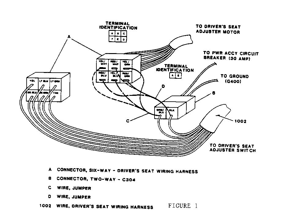
DRIVER'S SEAT ADJUSTER SWITCH (POWER) ------------------------------------- Figures 1 and 2 --------------- Refer to Figure 1: Using Jumper Wires for Raising Seat ------------------------------------------------------ Remove or Disconnect -------------------- 1. Separate six-way connector (A) under driver's seat (Figure 1).
2. Backprobe two-way connector C304 (B) terminal "A" (ORN/BLK wire) with a jumper wire (C-SOLID). Connect other end of jumper wire to six-way connector (A-motor side) terminal "C" (YEL/GRN wire) (Figure 1).
IMPORTANT: Be careful not to short power and ground circuits by touching the two jumper wires together. If circuits are accidentally shorted, the PWR ACCY (30 AMP) circuit breaker in the convenience center will probably open. Should this occur, wait until the circuit breaker has cooled and closed to continue procedures.
3. Backprobe two-way connector C304 (B) terminal "B" (BLK wire) with a jumper wire (D-SOLID). Connect other end of jumper wire to six-way connector (A-motor side) terminal "D" (RED/GRN wire) (Figure 1).
o Forward/back motor will begin to operate in the BACK direction with jumper wires connected. Allow motor to operate until seat is in the full BACK position.
4. Both jumper wires from six-way connector (A).
5. Connect jumper wire (C-LONG DASH) from two-way connector C304 (B) terminal "A" (ORN/BLK wire) to six-way connector (A-motor side) terminal "E" (YEL/BLU wire) (Figure 1).
6. Connect jumper wire (D-LONG DASH) from two-way connector C304 (B) terminal "B" (BLK wire) to six- way connector (A-motor side) terminal "F" (RED/BLU wire) (Figure 1).
o Front height motor will begin to operate in the UP direction with jumper wires connected. Allow motor to operate until front of seat is in the full UP position.
7. Both jumper wires from six-way connector (A).
8. Connect jumper wire (C-SHORT DASH) from two-way connector C304 (B) terminal "A" (ORN/BLK wire) to six-way connector (A-motor side) terminal "A" (YEL/WHT wire) (Figure 1).
9. Connect jumper wire (D-SHORT DASH) from two-way connector C304 (B) terminal "B" (BLK wire) to six-way connector (A-motor side) terminal "B" (RED/WHT wire) (Figure 1).
o Rear height motor will begin to operate in the UP direction with jumper wires connected. Allow motor to operate until rear of seat is in the full UP position.
10. Both jumper wires (C and D) from both connectors (A and B).
11. Separate two-way connector C304 (B) (Figure 2).
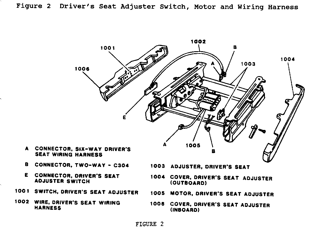
Refer to Figure 2: Driver's Seat Adjuster Switch, Motor and Wiring Harness -------------------------------------------------------------------------- 12. Using a thin 20 cm (8 inch) flat-bladed screwdriver, carefully reach under driver's seat and disconnect driver's seat adjuster switch connector (E) from driver's seat adjuster switch (1001 ) (Figure 2).
13. Using same 20 cm (8 inch) flat-bladed screwdriver, release locking tabs and remove driver's seat adjuster switch (1001 ) from adjuster cover (1006) (Figure 2).
Install or Connect
1. Driver's seat adjuster switch (1001 ) to adjuster cover (1006) (Figure 2). (Both the switch and the cover are indexed to prevent improper installation.)
2. Connector (E) to driver's seat adjuster switch (1001 ) (Figure 2).
3. Six-way connector (A) under driver's seat.
4. Two-way connector C304 (B) under driver's seat.
WARRANTY INFORMATION:
For vehicles repaired under warranty use:
Labour Operation: N2411 Labour Time: 0.4 HRS.
General Motors bulletins are intended for use by professional technicians, not a "do-it-yourselfer". They are written to inform those technicians of conditions that may occur on some vehicles, or to provide information that could assist in the proper service of a vehicle. Properly trained technicians have the equipment, tools, safety instructions and know-how to do a job properly and safely. If a condition is described, do not assume that the bulletin applies to your vehicle, or that your vehicle will have that condition. See a General Motors dealer servicing your brand of General Motors vehicle for information on whether your vehicle may benefit from the information.
