Headlamps/Interior Lights Dim Intermittently in Cold Weather (Replace Generator)

| Subject: | Headlamps/Interior Lights Dim Intermittently in Cold Weather (Replace Generator) |
| Models: | 1999-2002 Oldsmobile Intrigue with 3.5L V6 Engine (VIN H - RPO LX5) |
This bulletin is being revised to add VIN breakpoints and to include information on 2001-2002 vehicles which may exhibit a similar condition. Please discard Corporate Bulletin Number 01-06-03-001 (Section 06 - Engine).
Condition
Important: Short term voltage drops (flickers/fluctuations of lights) may occur whenever high demands are placed on the vehicle's electrical system. This is considered a normal generator output characteristic and a repair may not be necessary.
Some owners of the 1999-2001 model year Oldsmobile Intrigue built prior to VIN breakpoint 1F237068 may comment on an intermittent condition where the headlamps or interior lights may dim intermittently. This condition may also be noted in the blower speed slowing or changing pitch intermittently. Some 2001-2002 model year vehicles built after the VIN breakpoint may exhibit a similar condition.
Cause
On 1999-2001 vehicles built before the VIN breakpoint, this condition may be caused by intermittent low voltage. Transient engine vibrations may induce the generator to experience field discontinuity. This state results in a voltage spike that causes the voltage regulator to reset. During this period, the electrical system drops to battery voltage.
On 2001-2002 vehicles built after the VIN breakpoint, the voltage drop may be due to the electric AIR (Air Injector Reactor) pump cycling. This electric pump causes a large current draw when it starts.
Important: At no time during the above conditions will the headlamps go out.
Correction
On 1999-2001 vehicles built before the VIN breakpoint, replace the generator with a revised generator, P/N 10464469, that has circuitry to inhibit the voltage regulator reset condition. Use the procedure below to replace the generator.
On 2001-2002 models built after the VIN breakpoint, do not attempt any repair to the vehicle. This is a normal condition of the vehicle and does not indicate the need for service. If the customer requires reassurance that this is a normal condition, please refer to the AIR pump demonstration section below.
Important: 2000 model year California and Northeast states emission equipped vehicles and all 2001 Intrigues are equipped with the electric AIR pump. After generator replacement, these vehicles may still exhibit very short dips and/or headlamp dimming due to the AIR pump cycling. Refer to DTC P0410 in the Engine Controls sub-section. If the generator has been replaced, any short term headlamp dip should be considered normal. If the customer returns a vehicle that has been corrected with a generator replacement, you may reassure the customer by demonstrating the condition. Refer to the AIR pump demonstration section below.
- Open the hood and install fender covers.
- Remove the right front fender brace.
- Disconnect the negative and positive battery cables.
- Remove the underhood electrical center from the strut tower and reposition the electrical center.
- Remove the engine mount strut bracket.
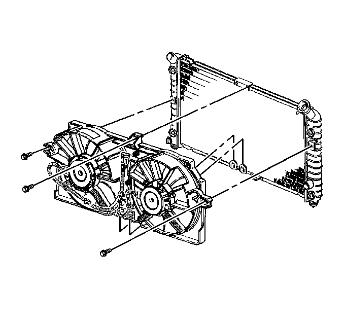
- Remove the main electrical connector to the cooling fans and the bolts retaining the cooling fan assembly. Refer to Figure 1.
- Remove the battery hold down bolt and remove the battery.
- Remove the bolts retaining the battery tray and remove the tray.
- Disconnect the IAT air tube.
- Remove the upper air filter housing and filter element.
- Remove the air filter housing assembly screws. Reposition the PCM and remove the air box.
- Disconnect the cooling fan assembly cross-car wire harness clips and reposition it, allowing the cooling fans to be lifted out of the vehicle. Remove the fan assembly.
- The radiator drain will now be accessible from the engine compartment. Place a catch pan under the vehicle. Drain the coolant.
- Disconnect the electrical connector from generator.
- Reposition the protective boot to access the generator output BAT terminal nut.
- Remove the generator output BAT terminal nut and reposition the battery positive lead.
- Remove the serpentine accessory drive belt.
- Remove the bolts from the thermostat housing and remove the housing.
- Remove the radiator to thermostat coolant hose.
- Close the radiator drain valve.
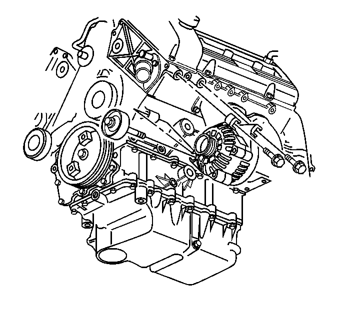
- Remove the idler pulley through-bolt. Refer to Figure 2.
- Remove the two remaining generator retaining bolts and remove the generator from the vehicle.
- Clean the mating surface on the engine block
- Install the new generator with the two bolts.
- Install the idler pulley with one bolt.
- Install the thermostat housing and bolts. Inspect the reusable gasket when reinstalling the housing. If any imperfection is shown on the O-ring gasket, replace it with a new one. Coat the threads of the bolts with pipe sealant, GM P/N 12346004 (in Canada, P/N 10953480) or the equivalent.
- Install the lower radiator hose to the thermostat housing.
- Install the serpentine accessory drive belt.
- Connect the electrical harness to the generator.
- Install the battery positive lead and the nut to the generator.
- Reposition the BAT terminal nut protective boot.
- Install the cooling fans and secure with the bolts.
- Connect the cross-car wiring harness clips and attach to the top of the radiator. Connect one engine cooling fan electrical connector.
- Install the air filter housing assembly and install the PCM to the air box.
- Install the upper air filter housing and the filter element.
- Install the battery tray and the bolts.
- Install the battery.
- Install the battery hold-down bolt.
- Install the engine mount strut bracket.
- Install the front right fender brace.
- Connect the positive and the negative battery cables.
- Refill the system with engine coolant.
- Bleed the cooling system. Refer to Bleeding the Cooling System in the Engine Cooling sub-section in the Service Manual.
- Remove the fender covers and close the hood.
Figure 1

Important: When removing the battery, do no tip it more than 40 degrees towards its sides.
Important: Even with the radiator drain open and the coolant recovery bottle cap off, a considerable amount of coolant will remain in the engine block. Place a large recovery tray under the vehicle at the thermostat location to capture this additional coolant.
Figure 2

Tighten
Tighten the generator and the idler pulley bolts to 50 N·m
(37 lb ft).
Notice: You must coat the threads of the thermostat housing bolts with Pipe Sealant, GM P/N 12346004 (in Canadian, P/N 10953480) or the equivalent. Coolant may walk up the threads creating a coolant leak if the sealer is not applied.
Tighten
Tighten the thermostat housing bolts to 9 N·m (80 lb in).
Tighten
Tighten the nut to 20 N·m (15 lb ft).
Tighten
| • | Tighten the radiator bracket bolt to 10 N·m (89 lb in). |
| • | Tighten the cooling fan shroud bolts to 6 N·m (53 lb in). |
Tighten
Tighten the negative and the positive battery terminal bolts to 15 N·m
(11 lb ft).
AIR Pump Demonstration
- Using the Tech 2® Diagnostic scan tool, connect the DLC connector to the vehicle and establish communications.
- After entering the vehicle information, select the Powertrain option.
- Select the Special Functions menu.
- Select Engine Output Controls.
- Select AIR System.
- From this screen you may command the AIR pump on and off. Turn the headlamps on. You will now be able to verify and demonstrate this normal operation to your customer.
- Exit the Tech 2® and disconnect the DLC connector.
Parts Information
Part Number | Description |
|---|---|
12553364 | Seal, Thermostat Housing |
10464469 | Generator Assembly |
Parts are currently available from GMSPO.
Warranty Information
For vehicles repaired under warranty, use:
Labor Operation | Description | Labor Time |
|---|---|---|
J4100 | Generator - Replace | Use Published Labor Operation Time |
Add | For Demonstration of Expected Condition | 0.1 hr |
