| Table 1: | Fan Relay Operation Matrix |
| Table 2: | Cooling Fan Relay 1 |
| Table 3: | Cooling Fan Relay 2 |
| Table 4: | Cooling Fan Relay 3 |
| Table 5: | Cooling Fan Functional Check |
| Table 6: | Cooling Fan Symptom Table 1 |
| Table 7: | Cooling Fan Symptom Table 2 |
| Table 8: | Cooling Fan Symptom Table 3 |
| Table 9: | Cooling Fan Symptom Table 4 |
| Table 10: | Cooling Fan Symptom Table 5 |
Refer to
Engine Cooling Fan Controls
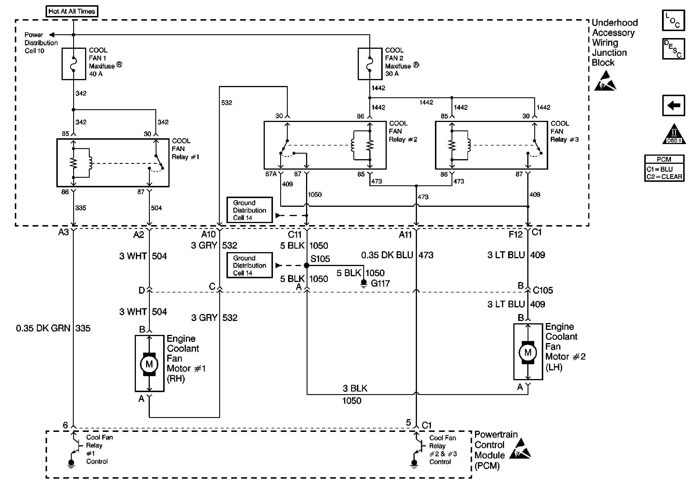
for
wiring diagram.
Circuit Description
The Electric Cooling Fan system consists of two electric cooling fans and three fan relays which are controlled by the PCM. The relays are wired in a series/parallel arrangement that allows the PCM to operate both fans together at low or high speed.
During low speed operation, the PCM grounds the control circuit for Fan Relay #1. The relay supplies current to the Fan 1 motor. The ground path for Fan 1 is through Fan Relay #2, through the Fan 2 motor to ground. The result is a series circuit with both fans running at low speed.
To command high speed cooling fan operation the PCM first grounds the control circuit for Fan Relay #1. After a 3 second delay, the PCM grounds the control circuit for Fan Relay #2 and Fan Relay #3. With Fan Relay #2 energized, both the primary and the secondary fan each have their own ground path creating a parallel circuit. This causes both fans to operate at high speed.
To determine if a fault is present perform the Cooling Fan Functional Check. If DTC P0480 or P0481 is set, or either DTC sets during the functional check, the DTCs must be diagnosed before proceeding with any of the symptom tables. Due to the complex nature of the fan circuit, various symptoms result depending where a fault occurs within the system.
The PCM commands Low Speed Fans on under the following conditions:
| • | Engine coolant temperature exceeds approximately 106°C (229°F). The fans will switch from low to off when the coolant drops below 102°C (216°F). |
| • | A/C operation is requested. |
| • | After the vehicle is shut off if the coolant temperature at key-off is more than 151°C (304°F) and system voltage is more than 12 volts. The fans will stay on for approximately 3 minutes. |
The PCM switches the fans to High Speed under the following conditions:
| • | Engine coolant temperature reaches 112°C (234°F). |
| • | A/C Refrigerant pressure exceeds 240 psi. The fans will return to low speed operation if the refrigerant pressure drops below 190 psi. |
| • | When certain DTCs set. |
If the cooling fans operate when commanded off and no DTCs are set, either a cooling fan relay is stuck on or a cooling fan circuit is shorted to power.
Whenever a repair is completed repeat the Cooling Fan Functional Check. The functional check will confirm proper system operation as well as help diagnose possible multiple failures, for example: two water contaminated relays.
Operational Mode | Fans Off | Low Speed Fans | High Speed Fans |
Fan Relay #1 | De-Energized | Energized | Energized |
Fan Relay #2 | De-Energized | De-Energized | Energized |
Fan Relay #3 | De-Energized | De-Energized | Energized |
Diagnostic Aids
If the cooling fans operate when commanded off and no DTCs are set, either a cooling fan relay is stuck on or a cooling fan circuit is shorted to power.
Several circuits (or a portion of a circuit) are part of the Underhood Accessory Wiring Junction Block. Typically if a problem is narrowed down to a circuit that is found within the Underhood Accessory Wiring Junction Block, the entire junction block must be replaced.
If the problem is intermittent refer to Intermittent Conditions
Relay Terminal Identification
Use the following relay cavity tables in order to locate the correct cavities to probe during diagnosis. The table layout corresponds to the cavity layout in the Underhood Accessory Wiring Junction Block. Four blade relays can be inserted two ways. Use the table and NOT the numbering on the relay to avoid probing incorrectly.
Important: Relay #2 is different (5 blade) from Relays #1 and #3 (4 blade). If Relay #2 is incorrectly replaced by a 4 blade style relay, the system will not function properly.
Top of Junction Block | |
|---|---|
Switch Load (Fan 1) | Coil Ground (PCM) |
Coil Power (Fuse) | Switch Power (Fuse) |
Top of Junction Block | |
|---|---|
Switch Power (From Fan 1) | Coil Ground (PCM) |
-- | Switch Load (Fan 2) |
Coil Power (Fuse) | Switch Ground |
Top of Junction Block | |
|---|---|
Switch Power (Fuse) | Coil Power (Fuse) |
Coil Ground (PCM) | Switch Load (Fan 2) |
Test Description
Number(s) below refer to the step number(s) on the Functional Check Table.
-
The Powertrain OBD System Check must be performed first so that mis-diagnosis is avoided. The PCM may be commanding the fans on due to a DTC being set, etc.
-
This verifies whether or not there is a fault on the cooling fan relay control circuits.
-
This step is checking to see if any A/C DTCs set. The PCM will turn on the cooling fans when certain DTCs are set. These must be diagnosed before proceeding with the Cooling Fan Functional Check.
-
This step is a functional test of the system in order to determine the symptom (if any) present.
Step | Action | Value(s) | Yes | No | ||||||
|---|---|---|---|---|---|---|---|---|---|---|
Did you perform the Powertrain On-Board Diagnostic (OBD) System Check? | -- | |||||||||
Did either Fan Relay Driver DTC set? | 5°C - 100°C (41°F - 212°F) | Go to the appropriate DTC. | ||||||||
With the engine idling turn A/C on to maximum cooling. Have any other DTCs failed this ignition? | -- | Go to the appropriate DTC | ||||||||
Do both cooling fans operate as commanded? | 100°C (212°F) | System OK | ||||||||
5 | Does either cooling fan operate when all fans are commanded Off? | -- | Refer to Diagnostic Aids. | |||||||
6 | Does only Cooling Fan #1 (right) operate with Fans Low Speed commanded On, then both fans operate when Fans High Speed is commanded On? | -- | ||||||||
7 | Repair CKT 532 shorted to ground. Is the repair complete? | -- | -- | |||||||
8 | Does neither cooling fan operate with Fans Low Speed commanded On, and then only Cooling Fan #2 (left) operates with Fans High Speed commanded On? | -- | Go to Cooling Fan Symptom Table 1 | |||||||
9 | Does neither cooling fan operate with Fans Low Speed commanded On, and then only Cooling Fan #1 (right) operates with Fans High Speed commanded On? | -- | Go to Cooling Fan Symptom Table 2 | |||||||
10 | Do both cooling fans operate with Fans Low Speed commanded On, and then only Cooling Fan #2 (left) operates with Fans High Speed commanded On? | -- | Go to Cooling Fan Symptom Table 3 | |||||||
11 | Do both cooling fans operate with Fans Low Speed commanded On, and then only Cooling Fan #1 (right) operates with Fans High Speed commanded On? | -- | Go to Cooling Fan Symptom Table 4 | |||||||
12 | Does neither cooling fan operate with Fans Low Speed commanded On, then both fans operate when Fans High Speed is commanded On? | -- | Go to Cooling Fan Symptom Table 5 | |||||||
13 | Does neither cooling fan operate when Fans Low Speed or Fans High Speed is commanded On? | -- | Refer to Diagnostic Aids. | |||||||
14 | Repair the open ground circuit between G117 and the splice. Is the action complete? | -- | -- |
Step | Action | Value(s) | Yes | No |
|---|---|---|---|---|
DEFINITION: No low speed operation of either cooling fan. High speed operation of cooling fan #2 (left) only. No DTCs set. | ||||
1 | Did you perform the Cooling Fan Diagnosis Functional Check? | -- | Go to the Electric Cooling Fan Diagnosis Functional Check. | |
2 |
Is the voltage near the value specified? | B+ | ||
3 | Jumper Cooling Fan #1 connector terminals A and B together. Does Cooling Fan #2 operate? | -- | ||
4 |
Is the voltage near the value specified? | B+ | ||
5 |
Is the voltage near the value specified? | B+ | ||
6 |
Is the voltage near the value specified? | B+ | ||
7 | Replace Cooling Fan #1 (right). Is the action complete? | -- | Go to the Electric Cooling Fan Diagnosis Functional Check for repair verification. | -- |
8 | Repair the open in CKT 504 between Cooling Fan #1 and Fan Relay #1. Is the action complete? | -- | Go to the Electric Cooling Fan Diagnosis Functional Check for repair verification. | -- |
9 | Replace Fan Relay #2. Is the action complete? | -- | Go to the Electric Cooling Fan Diagnosis Functional Check for repair verification. | -- |
10 | Repair the open in CKT 342 between Fan Relay #1 and the splice. Is the action complete? | -- | Go to the Electric Cooling Fan Diagnosis Functional Check for repair verification. | -- |
11 | Replace Fan Relay #1. Is the action complete? | -- | Go to the Electric Cooling Fan Diagnosis Functional Check for repair verification. | -- |
12 | Repair the open in CKT 532 between Fan Relay #2 and Cooling Fan #1. Is the action complete? | -- | Go to the Electric Cooling Fan Diagnosis Functional Check for repair verification. | -- |
Step | Action | Value(s) | Yes | No |
|---|---|---|---|---|
DEFINITION: No low speed operation of either cooling fan. High speed operation of cooling fan #1 (right) only. No DTCs set. | ||||
1 | Did you perform the Cooling Fan Diagnosis Functional Check? | -- | Go to the Electric Cooling Fan Diagnosis Functional Check. | |
2 |
Does Cooling Fan #1 (right) operate? | -- | ||
3 |
Is the voltage near the value specified? | B+ | ||
4 | Replace Cooling Fan #2 (left). Is the action complete? | -- | Go to the Electric Cooling Fan Diagnosis Functional Check for repair verification. | -- |
5 | Repair the open ground circuit to Cooling Fan #2 (left). Is the action complete? | -- | Go to the Electric Cooling Fan Diagnosis Functional Check for repair verification. | -- |
6 | Repair the open in CKT 409 between Cooling Fan #2 (left) and Fan Relay #2. Is the action complete? | -- | Go to the Electric Cooling Fan Diagnosis Functional Check for repair verification. | -- |
Step | Action | Value(s) | Yes | No |
|---|---|---|---|---|
DEFINITION: Low speed operation of both fans. High speed operation of cooling fan #2 (left) only. No DTCs set. | ||||
1 | Did you perform the Cooling Fan Diagnosis Functional Check? | -- | Go to the Electric Cooling Fan Diagnosis Functional Check. | |
2 |
Is the voltage near the value specified? | B+ | ||
3 |
Is the resistance the same or less than the value specified? | 5 ohms | ||
4 |
Do both cooling fans operate? | -- | ||
5 | Repair the open in CKT 1442 between Fan Relay #2 and the splice. Is the action complete? | -- | Go to the Electric Cooling Fan Diagnosis Functional Check for repair verification. | -- |
6 | Repair the open in CKT 473 between Fan Relay #2 and the splice. Is the action complete? | -- | Go to the Electric Cooling Fan Diagnosis Functional Check for repair verification. | -- |
7 | Repair the open in the ground circuit between Fan Relay #2 and the splice. Is the action complete? | -- | Go to the Electric Cooling Fan Diagnosis Functional Check for repair verification. | -- |
8 | Replace Fan Relay #2. Is the action complete? | -- | Go to the Electric Cooling Fan Diagnosis Functional Check for repair verification. | -- |
Step | Action | Value(s) | Yes | No |
|---|---|---|---|---|
DEFINITION: Low speed operation of both fans. High speed operation of cooling fan #1 (right) only. No DTCs set. | ||||
1 | Did you perform the Cooling Fan Diagnosis Functional Check? | -- | Go to the Electric Cooling Fan Diagnosis Functional Check. | |
2 |
Is the voltage near the value specified on both circuits? | B+ | ||
3 |
Is the resistance the same or less than the value specified? | 5 ohms | ||
4 | Jumper Fan Relay #3 CKT 1442 and CKT 409 together. Does Cooling Fan #2 (left) operate? | -- | ||
5 | Repair the affected leg of CKT 1442 between Fan Relay #3 and the splice. Is the action complete? | -- | Go to the Electric Cooling Fan Diagnosis Functional Check for repair verification. | -- |
6 | Repair the open in CKT 473 between Fan Relay #3 and the splice. Is the action complete? | -- | Go to the Electric Cooling Fan Diagnosis Functional Check for repair verification. | -- |
7 | Repair the open in CKT 409 between Fan Relay #3 and the splice. Is the action complete | -- | Go to the Electric Cooling Fan Diagnosis Functional Check for repair verification. | -- |
8 | Replace Fan Relay #3. Is the action complete? | -- | Go to the Electric Cooling Fan Diagnosis Functional Check for repair verification. | -- |
Step | Action | Value(s) | Yes | No |
|---|---|---|---|---|
DEFINITION: No low speed operation of either cooling fan. High speed operation of both fans. No DTCs set. | ||||
1 | Did you perform the Cooling Fan Diagnosis Functional Check? | -- | Go to the Electric Cooling Fan Diagnosis Functional Check. | |
2 | Verify that Fan Relay #2 is the correct part. Fan Relay #2 is a 5 pin relay. 4 pin relays (like Fan Relay #1 and #3) will plug in to the connector, however, the system will have this symptom. Was a problem found? | -- | ||
3 |
Do both fans now operate at low speed? | -- | ||
4 | Replace Fan Relay #2 with the correct relay. Is the action complete? | -- | Go to the Electric Cooling Fan Diagnosis Functional Check for repair verification. | -- |
5 | Replace Fan Relay #2. Is the action complete? | -- | Go to the Electric Cooling Fan Diagnosis Functional Check for repair verification. | -- |
6 | Repair CKT 409 between Fan Relay #2 and the splice. Is the action complete? | -- | Go to the Electric Cooling Fan Diagnosis Functional Check for repair verification. | -- |
