Driver or Passenger Seat Replacement Buick/Oldsmobile
Removal Procedure
- Remove the fasteners that retain the floor support covers.
- Remove the floor support covers.
- Remove the load bar cover.
- Move the seat to the full rearward position.
- Remove the front floor support covers.
- Remove the front nuts that retain the adjuster to the floor pan.
- Move the seat to the full forward position.
Caution: On seats with a manual adjuster, failure to place the seat in the full
forward position prior to removal of the rear attaching nuts could allow the
seat track to suddenly spring forward, resulting in personal injury.
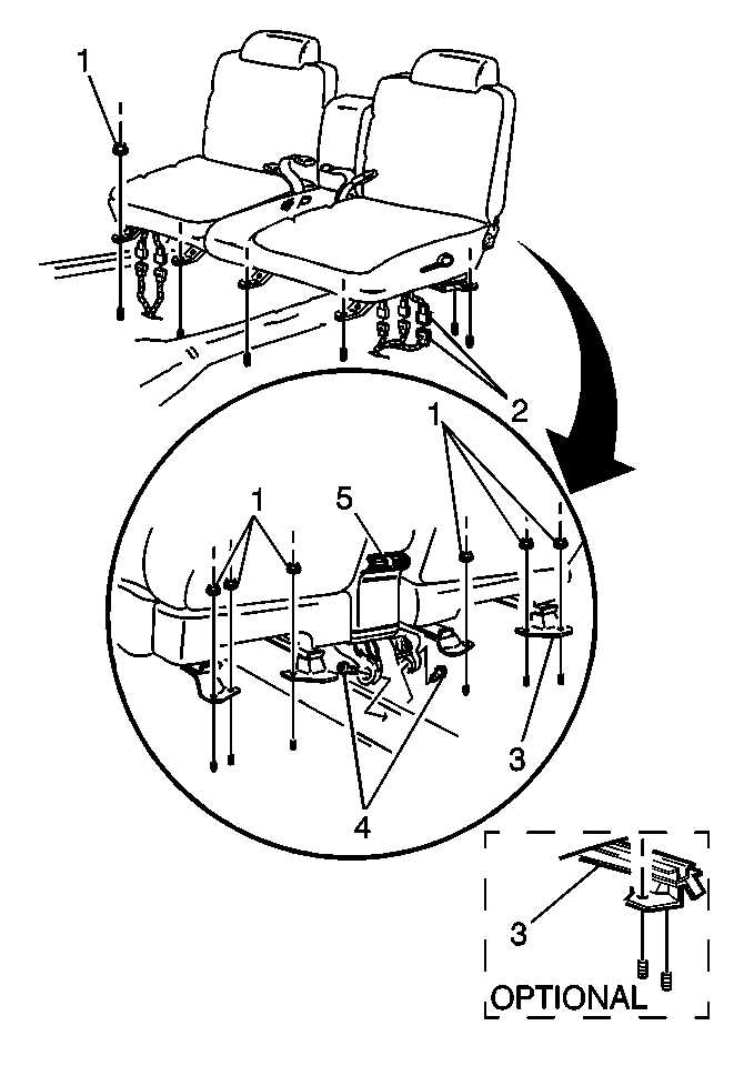
- Remove the rear nuts that retain the adjuster (3) to the floor
pan. (The insert shows the manual adjuster.)
- Remove the load bar bolt (4).
- Tilt the seat forward.
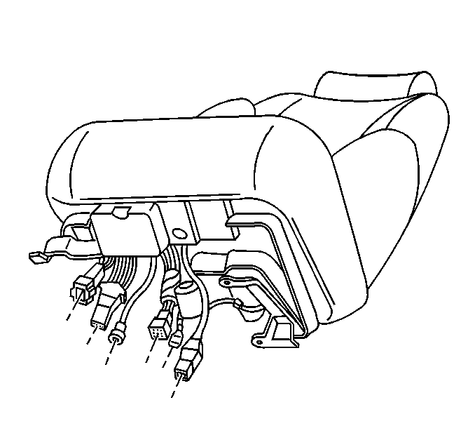
- Disconnect the following components:
| • | The electrical connectors (2) |
| • | The air hose (if equipped) |
| • | The HVAC duct (5) at the armrest (if equipped) |
- Remove the rear seat cushion, prior to front seat removal. Refer
to
Rear Seat Cushion Replacement
.
- Remove the left front seat out the left rear door, with the aid
from an assistant.
Installation Procedure
- Install the front seat,
with the aid from an assistant, through the left rear door opening.
- Install the rear seat cushion. Refer to
Rear Seat Cushion Replacement
in Seats.
- Connect or install the following components:
| • | The electrical connectors (2) |
| • | The air hose (if equipped) |
| • | The HVAC duct (5) at the armrest (if equipped) |
Notice: Use the correct fastener in the correct location. Replacement fasteners
must be the correct part number for that application. Fasteners requiring
replacement or fasteners requiring the use of thread locking compound or sealant
are identified in the service procedure. Do not use paints, lubricants, or
corrosion inhibitors on fasteners or fastener joint surfaces unless specified.
These coatings affect fastener torque and joint clamping force and may damage
the fastener. Use the correct tightening sequence and specifications when
installing fasteners in order to avoid damage to parts and systems.
- Install the load
bar bolt (4).
Tighten
Tighten the load bar bolt to 35 N·m (26 lb ft).
- Install the rear nuts in order to attach the adjuster (3)
to the floor pan. (The insert shows the manual adjuster).
Tighten
Tighten the rear nuts to 34 N·m (25 lb ft).
- Install the front nuts in order to attach the adjuster (3)
to the floor pan. (The insert shows the manual adjuster.)
Tighten
Tighten the front nuts to 34 N·m (25 lb ft).
- Move the seat to the full
forward position.
- Install the load bar cover.
- Install the floor support covers front and rear.
- Install the floor support cover fasteners front and rear.
Driver or Passenger Seat Replacement Pontiac
Removal Procedure
- Remove the fasteners that
retain the floor support covers.
- Remove the floor support covers.
- Remove the load bar cover.
- Move the seat to the full rearward position.
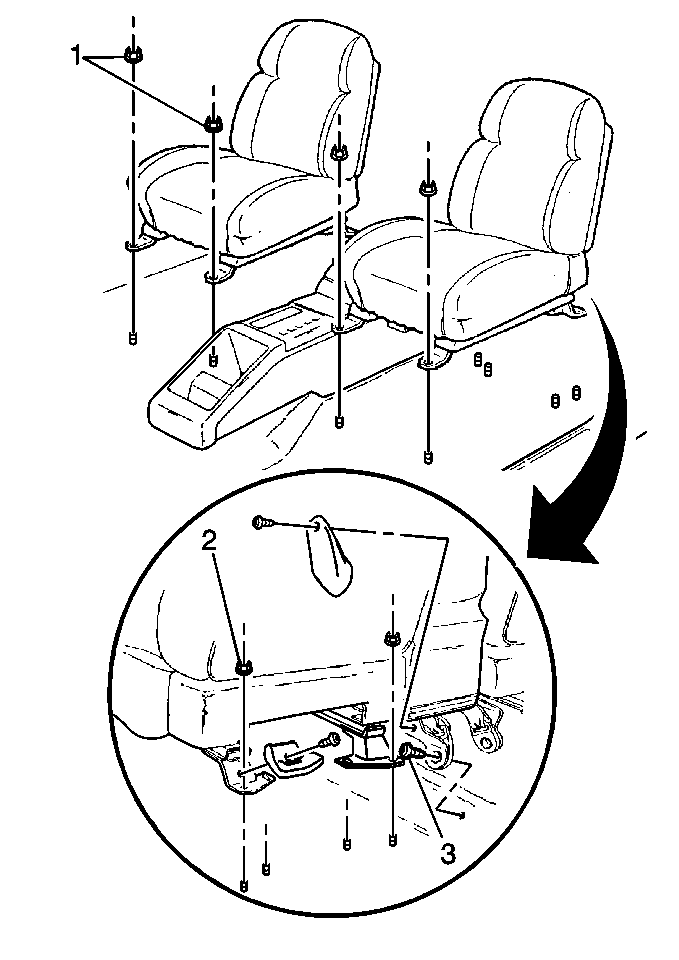
- Remove the front nuts (1) that attach the adjuster to the
floor pan.
- Move the seat to the full forward position.
Caution: On seats with a manual adjuster, failure to place the seat in the full
forward position prior to removal of the rear attaching nuts could allow the
seat track to suddenly spring forward, resulting in personal injury.
- Remove the rear nuts (2) that attach the adjuster to the floor
pan.
- Remove the load bar bolt (3).
- Tilt the seat
rearward.
- Disconnect the following components:
| • | The electrical connectors |
| • | The HVAC duct at the armrest, where applicable. |
- Remove the seat with aid from an assistant.
Installation Procedure
- Install the seat with
aid from an assistant.
- Connect or install
the following components:
| • | The electrical connectors (2) |
| • | The HVAC duct at the armrest, where applicable. |
Notice: Use the correct fastener in the correct location. Replacement fasteners
must be the correct part number for that application. Fasteners requiring
replacement or fasteners requiring the use of thread locking compound or sealant
are identified in the service procedure. Do not use paints, lubricants, or
corrosion inhibitors on fasteners or fastener joint surfaces unless specified.
These coatings affect fastener torque and joint clamping force and may damage
the fastener. Use the correct tightening sequence and specifications when
installing fasteners in order to avoid damage to parts and systems.
- Install the load
bar bolt (3).
Tighten
Tighten the load bar bolt to 42 N·m (31 lb ft).
- Install the rear nuts in order to attach the adjuster to the floor
pan.
Tighten
Tighten the rear nuts (2) to 34 N·m (25 lb ft).
- Install the front nuts in order to attach the adjuster to the
floor pan.
Tighten
Tighten the front nuts (1) to 34 N·m (25 lb ft).
- Move the seat to the full rearward position.
- Install the load bar cover.
- Install the floor support covers.
- Tighten the floor support cover fasteners.
