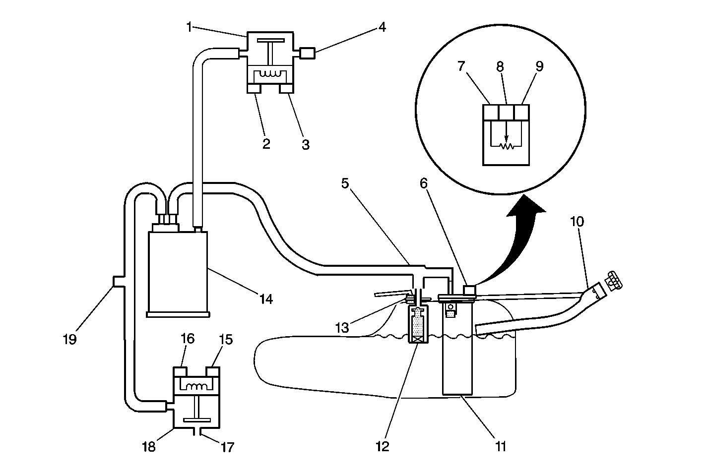
The Evaporative Emission (EVAP) control system limits the fuel vapors from escaping into the atmosphere. The EVAP transfers the fuel vapor from the sealed fuel tank to an activated carbon (charcoal) storage device (EVAP canister). The EVAP canister stores the vapors until the engine is able to use the extra fuel vapor.
When the engine is able to use the extra fuel vapor, the intake air flow purges the fuel vapor from the carbon element, and then the normal combustion process consumes the fuel vapor.
The system is required in order to detect the evaporative fuel system leaks as small as 0.040 between the fuel filler cap and the purge solenoid. The system can test the evaporative system integrity by applying a vacuum signal (ported or manifold) to the fuel tank in order to create a small vacuum.
The evaporative system includes the following components:
The POWERTRAIN CONTROL MODULE (PCM) supplies a ground to energize the valve (purge on). The EVAP canister purge valve control is Pulse Width Modulated (PWM) or turned on and off several times a second. The duty cycle (pulse width) is determined by engine operating conditions including load, throttle position, coolant temperature and ambient temperature. The duty cycle is calculated by the PCM and the output is commanded when the appropriate conditions have been met. The system checks for conditions that cause the EVAP system to purge continuously by commanding the EVAP canister vent valve on and the EVAP purge valve off (EVAP canister vent valve CLOSED, EVAP purge PWM 0%). If vacuum level in the fuel tank increases during the test, a continuous purge flow condition is indicated. This can be caused by any of the following conditions:
If any of these conditions are present, DTC P1441 will set.
A continuous open purge flow condition is detected during the diagnostic test (fuel tank pressure decreases to less than -11 in. H2O).
Important : Although these diagnostics are considered type A, they act like type B diagnostics under certain conditions. Whenever the EVAP diagnostics report that the system has passed, or if the battery has been disconnected, the diagnostic must fail during two consecutive cold start trips before setting a DTC. The initial failure is not reported to the diagnostic executive or displayed on a scan tool. A passing system always reports to the diagnostic executive immediately.
Check for the following conditions:
Reviewing the Fail Records vehicle mileage since the diagnostic test last failed may help determine how often the condition that caused the DTC to set occurs. This may assist in diagnosing the condition.
Number(s) below refer to the step number(s) on the Diagnostic Table:
If an EVAP purge valve electrical malfunction is present, the purge system will not operate correctly. Repairing the electrical malfunction will very likely correct the condition that set DTC P1441.
Checks the Fuel Tank Pressure sensor stuck high condition. The scan tool should read within 1.0 in H2O of the specified value.
Checks for a stuck open EVAP purge valve.
Verifies that the fuel tank pressure sensor accurately reacts to EVAP system pressure changes.
If the EVAP purge and engine vacuum lines are switched at the EVAP purge solenoid, the solenoid valve will leak vacuum.
The PCM will command the EVAP purge and EVAP canister vent valves closed with the scan tool Seal System EVAP output control function activated. Fuel tank pressure should not decrease under this condition.
Step
Action
Value(s)
Yes
No
1
Was the Powertrain OBD System Check performed?
--
Go to Step 2
Go to Powertrain On Board Diagnostic (OBD) System Check
2
Important: Visually/Physically inspect for the following conditions:
Is DTC P1665 Evaporative Emission (EVAP) Vent Solenoid Control Circuit or DTC P1676 Evaporative Emission (EVAP) Purge Solenoid Control Circuit also set?
Go to other DTCs First
Go to Step 3
3
Is the Fuel Tank Pressure at the specified value?
0 in. H2O
Go to Step 4
Go to Step 11
4
Important: : Before continuing with diagnosis, zero the EVAP Pressure and Vacuum (inches of H2O) gauges on the (1)Main Valve (2)Evaporative Emission System Purge/Presure Diagnostic Station J 41413 (3)Nitrogen Cylinder (4)Black Connecting Hose (5)Threaded Fitting (6)Gauge Set EVAP pressure/purge diagnostic station (refer to tool operating instructions).
Important: Do not exceed the pressure in the specified value.
Can the specified value be achieved?
5 in. H2O
Go to Step 5
Go to Step 6
5
Go to Diagnostic Aids
Go to Step 10
6
Check the EVAP purge and source vacuum line routing and connections at the EVAP purge valve. Refer to Emission Hose Routing Diagram .
Are the EVAP purge and source vacuum lines connected correctly at the EVAP purge valve?
Go to Step 7
Go to Step 9
7
Is vacuum level near the specified value?
0 in. Hg
Go to Step 8
8
Important: : Check for carbon release into the EVAP system. Refer to Diagnostic Aids.
Replace the EVAP canister purge valve/solenoid. Refer to Evaporative Emission Canister Purge Solenoid Valve Replacement or Evaporative Emission Canister Replacement .
Is the action complete?
Go to Step 12
9
10
Was a problem found?
Go to DTC P0452 Fuel Tank Pressure Sensor Circuit Low Voltage
11
Is action complete?
0 in H2O
Go to DTC P0453 Fuel Tank Pressure Sensor Circuit High Voltage
12
Does the EVAP pressure decrease to less than the second lower specified value within 3 minutes with the rotary switch in the "OFF/Hold" position?
15 in. H2O
10 in H2O
System OK