Removal Procedure
- Disconnect the negative battery cable. Refer to
Caution: Unless directed otherwise, the ignition and start switch must be in the OFF or LOCK position, and all electrical loads must be OFF before servicing
any electrical component. Disconnect the negative battery cable to prevent an electrical spark should a tool or equipment come in contact with an exposed electrical terminal. Failure to follow these precautions may result in personal injury and/or damage to
the vehicle or its components.
- Remove the console as necessary.
- Place the shift lever in (P) Park.
- Turn the ignition key to the RUN position.
- Remove the left sound insulator and the knee bolster as necessary.

Important: Do not attempt to perform the following steps with the key in any other
position.
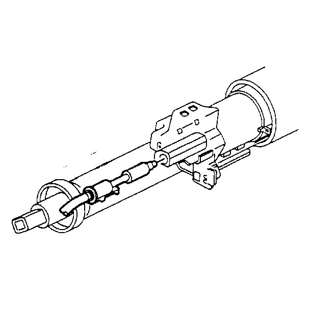
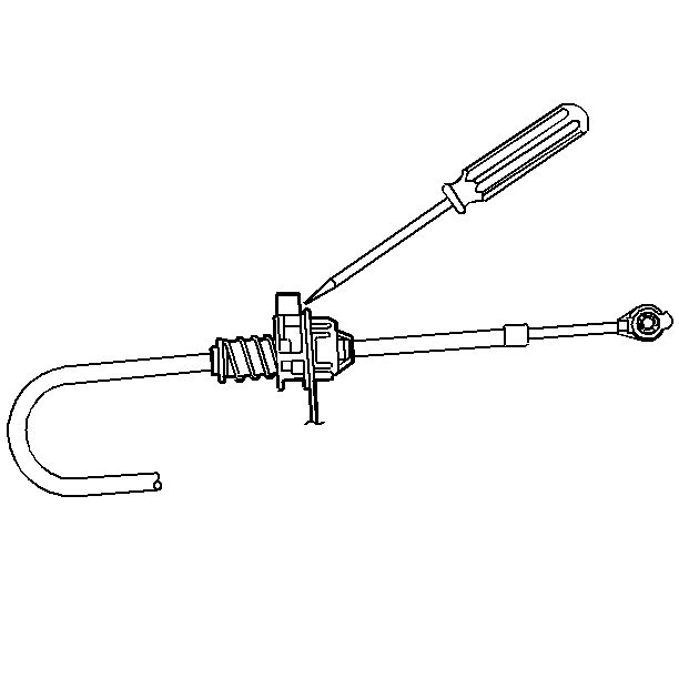
- Slip a screwdriver blade into the slot provided in the ignition switch
inhibitor.
- Depress the cable latch.
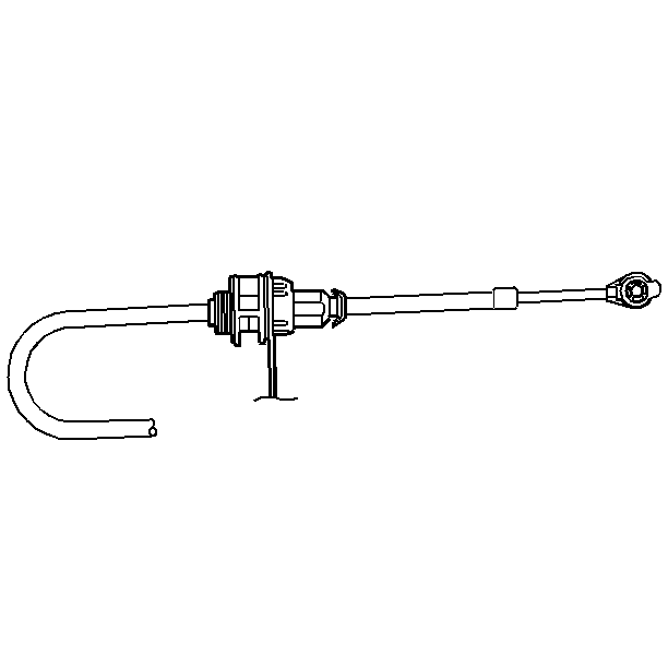
- Pull the cable from the inhibitor.
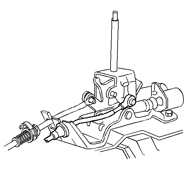
- Pull the cable adjuster locking button at the shift control bracket
to the UP position.

- Pull rearward on the cable
end in order to unsnap the cable from the park lock lever pin on the shift
control assembly.
- Depress the two cable adjuster tangs and remove from the shifter
control assembly.
- Remove the cable clips.
Installation Procedure

- With the cable adjuster
locking button in the UP position and the shift lever in the (P) Park position,
snap the cable connector into the shifter control bracket. Ensure that the
two cable adjuster tangs are fully engaged.
- With the ignition in the RUN position, snap the cable into the
inhibitor housing.
Important: Do not insert the cable with the key in any other position except RUN.
- Turn the ignition key to LOCK.
- Snap the cable end onto the park lock lever pin on the shift control
assembly.
- Complete the following steps in order to adjust the assembly:
- Ensure that the ignition key is in the LOCK position. If the key
can not be rotated to the LOCK position, lift the adjuster locking button
and slide the adjuster rearward in the car compressing the spring and hold.
Rotate the key in order to lock.

- Ensure that the cable
adjuster locking button is in the UP position.
- Grasp the park lock cable near the forward end of the adjuster
spring. Push the cable toward the front of the vehicle in order to remove
the slack and release.
- Move the cable adjuster rearward in the vehicle 1.5 mm
(1/16 in) from the position established in the previous step.

- While holding this position,
push the adjuster locking button down flush with the adjuster body.
- Install the left sound insulator and the knee bolster.
- Install the console.
- Connect the negative battery cable.
- In order to verify correct functional operation of the park lock
system, perform the following steps:
| 14.1. | Turn the ignition key to the OFF/LOCK position. |
| 14.2. | If you can shift out of (P) Park, readjust the park lock cable. |
| 14.3. | Turn the ignition key to the RUN position. |
| 14.4. | Shift to (N) Neutral. |
| 14.5. | If you can turn the ignition key to the OFF/LOCK position and
are able to remove the key, readjust the park lock cable. |
| 14.6. | Return the shifter to (P) Park. |
| 14.7. | Turn the ignition key to OFF/LOCK. |
| 14.8. | If you can not remove the key, readjust the park lock cable. |


