For 1990-2009 cars only
Disassembly Procedure
Tools Required
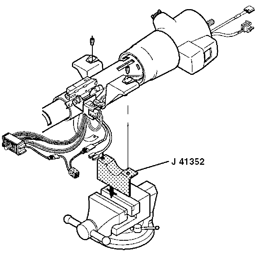
J 41352 Modular Column Holding Fixture
- The turn signal switch assembly must be in the "UP" position.
- Align the block tooth on the steering shaft assembly to the 12 o' clock position.
- Check steering column for accident damage. Refer to Steering Column Accident Damage Inspection - Off Vehicle .
- Place the ignition into the LOCK position to center the coil assembly.
- Install the steering column and J 41352 into a vise.
- Remove the wire harness assembly from the wire harness strap.
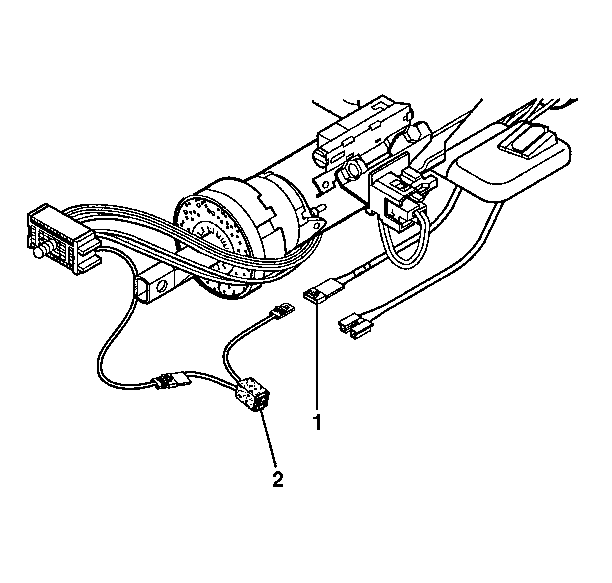
- Remove the SIR connector (1) from the fused jumper assembly connector (2).
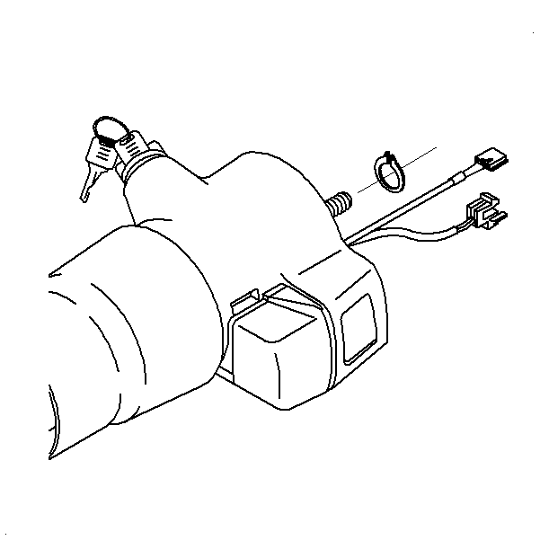
- Remove the retaining ring.
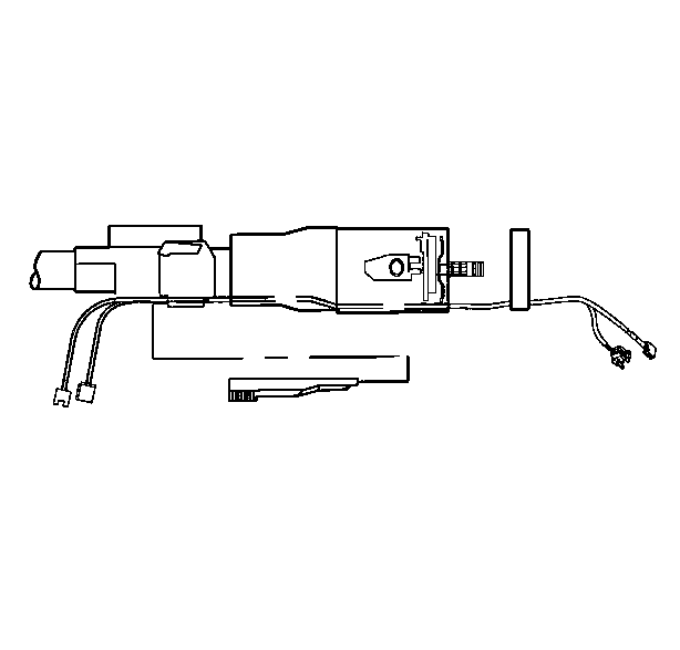
- Remove the wire protector.
- Attach a wire to the SIR coil assembly connector. Attaching a wire to the connector will make installation easier.
- Gently pull the SIR coil assembly and connector from the steering column.
Important: Check the fused jumper assembly for burnt 2 fuses before doing this procedure.


