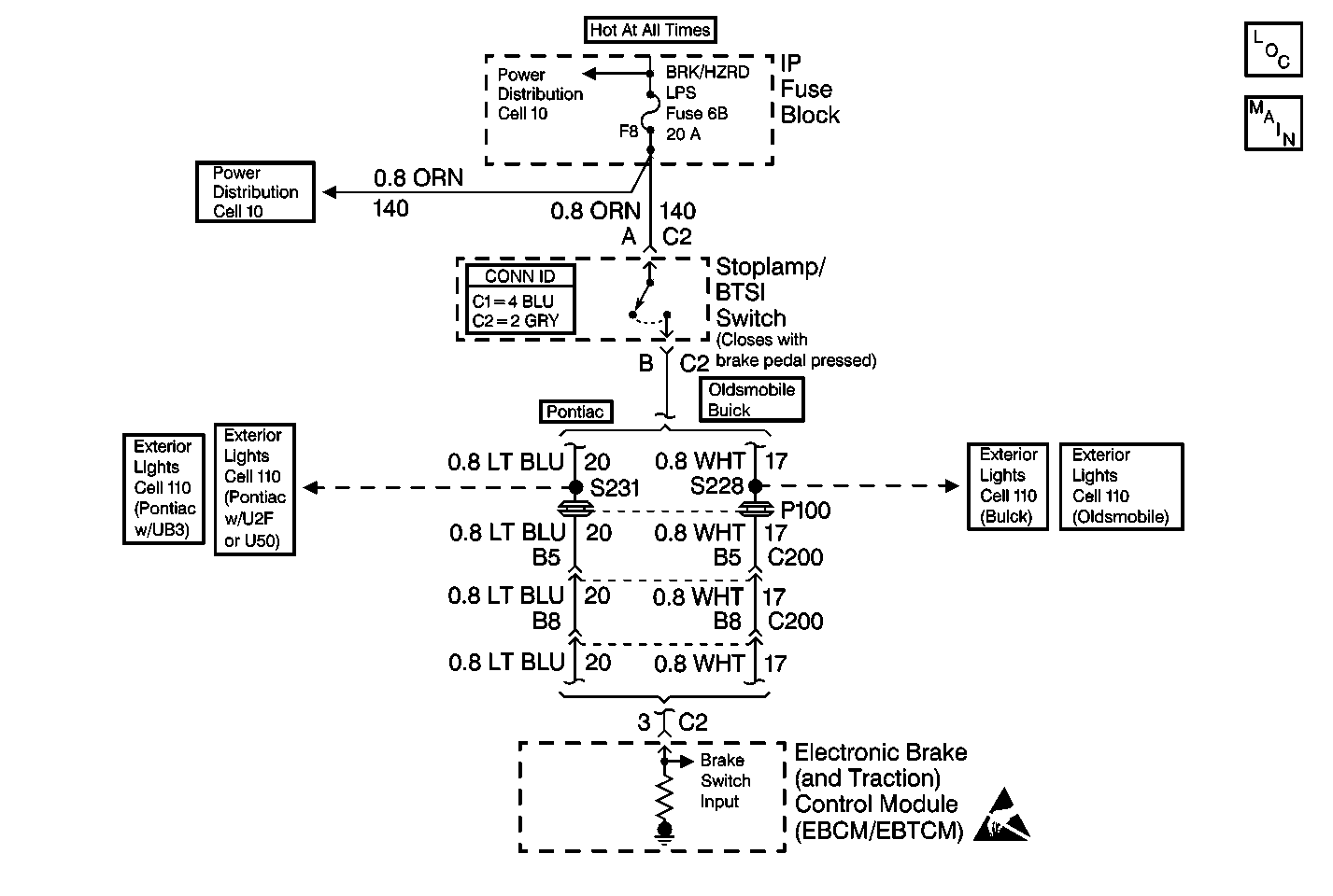
Circuit Description
This DTC is the second portion of DTC C1291. If DTC C1291 occurred during the last ignition cycle, DTC C1293 becomes a current malfunction during the next ignition cycle. This keeps the TCS disabled until a stoplamp switch ON state is detected. When a stoplamp switch ON state is detected during an ignition cycle in which DTC C1293 is a current malfunction, DTC C1293 will become a history DTC at the end of the current ignition cycle, and the TCS will enable at the start of the next ignition cycle. DTC C1293 alone indicates that DTC C1291 occurred previously, but is intermittent, or has been corrected.
Conditions for Setting the DTC
A DTC C1291 was set in a previous ignition cycle.
Action Taken When the DTC Sets
| • | A malfunction DTC is stored. |
| • | The TCS is disabled. |
| • | The TRACTION OFF indicator is turned ON. |
| • | The ABS remains functional. |
Conditions for Clearing the DTC
| • | The condition for the DTC is no longer present and you used the scan tool Clear DTC function. |
| • | The EBCM/EBTCM does not detect the DTC in 50 drive cycles. |
Diagnostic Aids
| • | If any wheel speed sensor DTCs are present, diagnose them first. Refer to Diagnostic Trouble Code (DTC) List . |
| • | It is very important that a thorough inspection of the wiring and connectors be performed. Failure to carefully and fully inspect wiring and connectors may result in misdiagnosis, causing part replacement with reappearance of the malfunction. |
| • | An intermittent can be caused by a poor connection, broken insulation, or a wire that is broken inside the insulation. |
| • | If an intermittent malfunction exists, refer to Intermittents and Poor Connections Diagnosis in Wiring Systems. |
| • | Verify proper stoplamp/BTSI switch operation using the data list of the scan tool. As the brake is applied, the data list displays the stoplamp/BTSI switch on within 1 inch of travel. |
Test Description
The numbers below refer to the step numbers on the diagnostic table.
Step | Action | Value(s) | Yes | No |
|---|---|---|---|---|
1 | Did you perform the ABS Diagnostic System Check? | -- | Go to Step 2 | |
Is DTC C1291 set as a history or current code? | -- | Go to DTC C1291 Open Brake Lamp Switch Contacts During Deceleration |
